The build of the ESP-12-in-circuit-adapter consists of the following steps:
- Attaching the resistors on the base bread board
- Glueing on the intermittend board with hot glue
- Cutting the rubber pad
- Glueing the rubber pad on
- Pre-pinning the holes of the contact wires
- Winding and cutting of the contact wires
Part 2:
- Fixing the conntact wires in the rubber pad
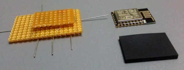
- Inserting the module to determine the distances
- Fixing the contact wires with hot glue
- Fixing the contact wires on the pin header side
- Fixing the angle pin header
- Glueing on the keys
Part 3:
- Soldering in the circuit wires
- Soldering in the pin headers
- Finalizing and test
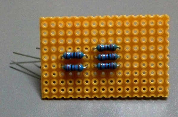
1. Attaching the resistors on the base bread board:
Bend the five resistors so they fit into the 7,62 mm grid. Add them to the board as shown in the image.
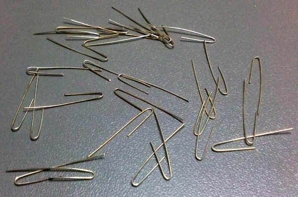
Bend the contact wires as shown below
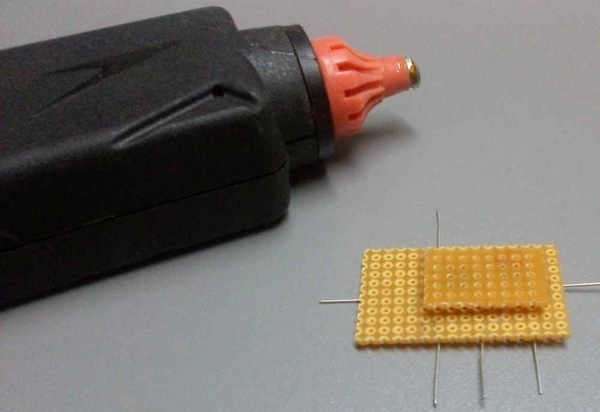
2. Glueing on the intermittend board with hot glue
Put the board with the resistors with the wire side and glue the small bread board with hot glue. The board needs to be centered. the front edge should align with the middle of the second hole line. Make sure the board is a little smaller than the distance in between left and right hole line of the esp module. Otherwise the needle will stuck at the board when pinning the rubber. See image below:
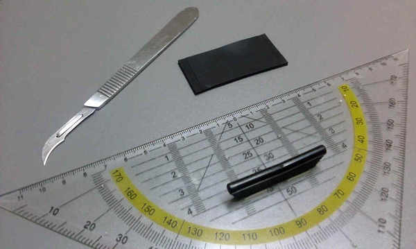
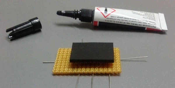
3. Cutting the rubber pad
The rubber pad will be cut with a scalpel with blade 12. Dimensions: 18,5 * 25 * 2 Tip: Put a ruler onto the rubber and never cut immediatlely completely through. Just scratch a little and go step by step deeper to prevent distortions. A droplet of soap water helps against stucking.
4. Glueing the rubber pad on
Glue the rubber pad onto the small board so that the front edge aligns with the front of the small board and the overstanding is equal on either other side.
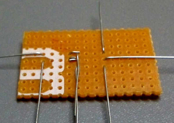
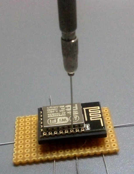
5. Pre-pinning the holes of the contact wires
The holes for the contact wires will be pre-pinned using a sewing needle. This step decides later the function of the adapter. Therefore you need to work very carefully and precise. As a pinning template te drilling hole of a ESP12E module will be used. Therefore the needle should just fit trough the holes without much play. Also you need to take care about the following:
- Later te contact wires will be pressed against the half holes of the ESP pads. It is recommended to pin the holes for 0.2 mm further on the outside, so the contact angle does not become too steep. Therefore shift the ESP module for about this amount to either side.
- When collaring the needle you still have a lot of play, because the needle is thinner on the tip. Her you need to take care you set the needle always at the same point. Tip: If you run down with the needle tip the outer rim of the hole downwards, the needle centers for its own and reaches always the same point.
- Pre-pin the diagonal contacts in a way, that you still have contact pressure. This means the module should be shifted a little to the front (approx. 0,2 mm).
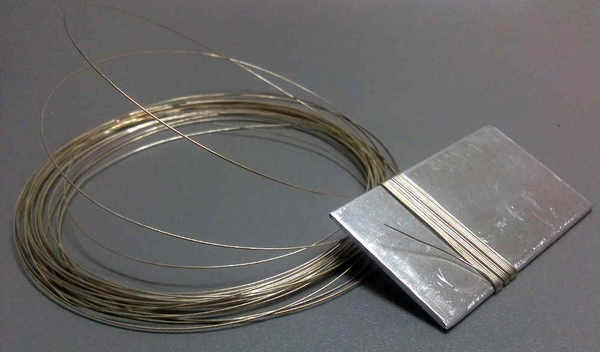
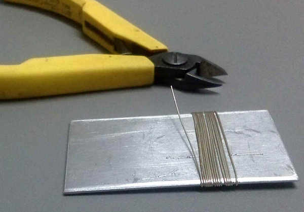
6. Winding and cutting of the contact wires
The contact wires may consist of siver plated copper wire or gold plated steel wire with a diameter of 0,45 mm and can be prepared and bent by yourself. Important: The contact wire needs to have springy properties. A soft silver wire may be too soft. You may harden a soft wire, by pulling it in between two pliers until it nearly rips. During this process the wire becomes much harder gets springy properties and becomes nicely straight.
To build the contact wires you need a piece of plate with a thickness of 2mm and a width of 65 mm. The edges should be rounded.
Now you wind the wire under tension around the plate – make approx. 15 winds – then a few contacts remain.
The windings you cut with wire cutting pliers on both side at a distance of 11 mm from the edges (rotation symetric). As a result you get the double number of pre-bent contact wires.