To improve the function of the hot end I did the following modifications:
- I disassmbled the heaters and the thermistors from the hot ends and placed them again with heat conduct paste in between. This is very helpful to keep the hot ent temperature more constant. Usually there is a gap inbetween the elements and that causes heat transmission problems.
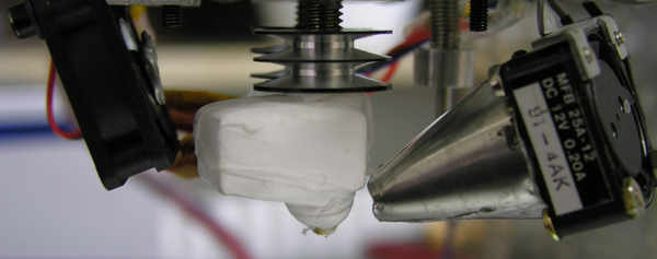
- I covered the hot end with ordinary teflon tape used for sealing tubes in water installations. Teflon tape contains some micro air bubbles to allow some compression of the tape for better sealing. In our case that helps a lot to isolate the hot end. Since teflon canwithstand temperatures of permanently 260° it is ferfect for that job. Also it is very easy to apply, because it can be stretched as needed. Fiddling around with KaptonTape is much more difficult and also more expensive. Especially for high temperatures the heating times dropped to about 50 % compared to un-isolated.
- I added heat sinks to the filament supply. Especially PLA tends to stuck inside the little teflon tube in the inner side of the mounting thread for the hot end heat block. This way the extruder cooling fan can do its work where it is supposed to (It actually shall not cool down the extruder, but the supply tube, so the filament gets not molten there and stucks inside).
- I took care not to have a gap in between the nozzle and the supply tube inside the heating block of the hot end. This is to prevent of filament resting in this gap and get burned over time. That means on the other hand, that the position of the cables from the hot end is partially by fortune because the two nozzles need exactly the same height over the print bed. Therefore I first adjusted the nozzles and then I decided how to position the hot end unit in the delta triangle and routed the cables.
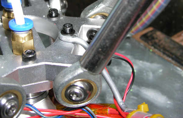
The nozzle positions need to be entered into the firmware. - I had difficukties to get the shaft sliding easy that trips the auto level switch. This is for my opinion a constructive problem, because the thickness of the delta triangle is simply too low to guide the shaft properly. Obviously Geeetech was aware of this, so they added a diamond file into the kit an leave it to the user to spoil the guide. Either the shaft stucks or it wobbles inside. So I modified the guide by drilling the hole bigger and glueing in a 4 x 0,5 mm brass tube with a length of approx. 15 mm. Now the shaft slides easy without play and doesn’t get stuck. The inner diameter of the spring pushing back the shaft is slightly larger than 4mm, so the operation is assured.
- I added a stiff piece of 3mm steel wire to tie the cables to. Without this the cables surely would break soon at the weakest point – see image below.