Properties of the electronics of the scale
The scale electronics consists of the following parts:
Required electronic components:
1 Arduino pro mini – I used one with Atmega 328p 16Mhz 5V
1 LCD Display 16 x 2 HD44780 with an I²C to Parallel converter PCF8574
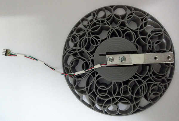
1 Weight cell 5 KG with HX711 Weight controller – best is to buy a kit.
1 Perforated board (electronics PCB) 19.5 mm x 50 mm in raster 2.54 mm
1 Battery connector with wires for 9V block battery
2 4 pin female pin header raster 2.54 mm
1 4 pin male pin header raster 2.54 mm
1 Voltage regulator AMS 1117 5V
1 Transistor BC516
2 Transistors BC 547
2 Diodes 1N4148
2 Micro keys / switches
2 Resistors 18K
1 Resistor 27K
1 Resistor 33K
1 Resistor 100K
1 Resistor 270K
1 Capacitor 10nF
1 Capacitor 100uF
1 Capacitor 10uF tantalum small size
1 Capacitor 47uF tantalum low leak current
Some very thin isolated wires to wire the circuits
Cyan acrylate glue
Here you may download the circuit diagram of the scale:
The 47uF capacitor is a bit critical. Here you have to take care to use a type with a very low leak current, because this has an effect on the switch on and switch off delay of the zero power circuit. To be safe, better use a tantalum type.
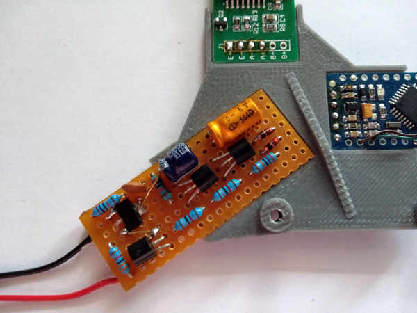
Zero power circuit:
To realize the zero power circuit, I used a perforated board.
See the photos furrther down to see how to wire it. The schematics you find the the attached PDF.
Make sure your components fit into the case. There is very little space, so if you use larger parts or you change the orinetation, you may run into trouble – so keep this in focus.
Operation buttons:
The operation keys or buttons are very small (5 x 5 x 1.5 mm) These are common buttons. The thickness is critical, because the mechanical space in between button support and front cover is optimized for these buttons. So try to get the same type. If you search on the internet for “micro SMD button” you will find a source. 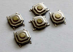
I glued two of these buttons using cyan acrylate glue onto the button support and applied some wires:
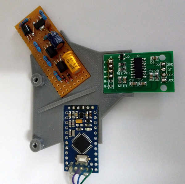
Weight controller PCB
During testing of the weight cell and its HX711 PCB I noticed, that the board is extremely sensitive to changes of the resistance of some parts. In fact, I had bad difficulties to get a stable output signal – the drift was quite high. Also I noticed, by breathing upon the circuit, the values changed dramatically. So I decided to cover the complete PCB with some transparent paint. After that the drift became very small.
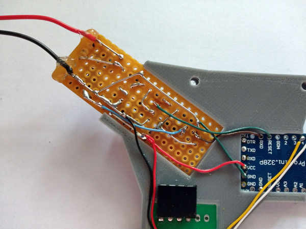
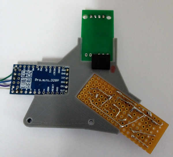
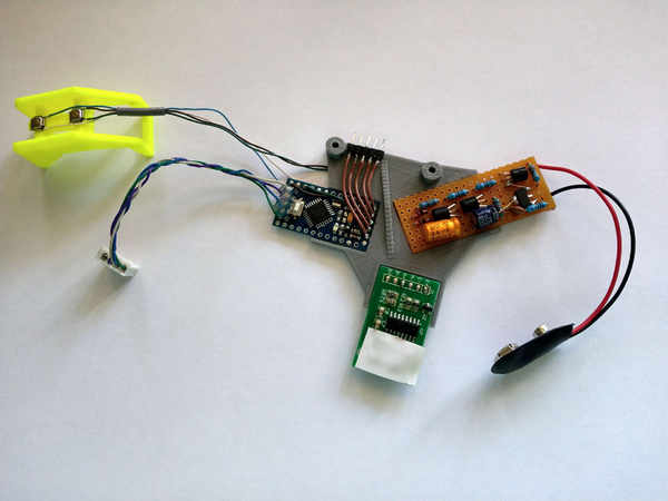
Wiring of the circuit:
After glueing the electronics PCBs into the PCB holder I wired the inter board connections using thin isolated wires according to the diagram – see the subsequent photos. On top of the weight cell controller board, I put a small piece of isolation tape, since the board is in mounted position very close to the display. Not respecting this, could cause short circuits …
Here you find the wiring diagram: