
How to build the surveillance camera
The build of the camera actually only requires just the power conditioning and the connecting of the USB cable – “actually”. As usually the devil sits inside the details.
Why ? Because:
- Notebook modules are build in SMD
- The connecting plug is difficult to get and a normal USB cable is too large to be mounted inside the plug
- The connecting points are too small to solder on an ordinary USB cable
- The power supply should be adapted to the size of the module
- The whole Unit should be mechanically stable
These problems I solved as follows:
- The USB cable will not be soldered directly onto the module and also no plug will be used
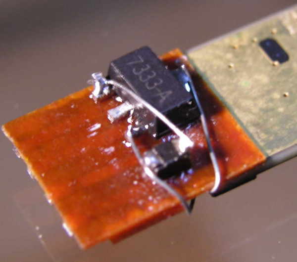
- Instead a small piece ap PCB material in the width of the module and a thickness of 0.5 mm will be glued onto the module using superglue
- On the lower side of the PCB the SMD parts (voltage regulator and tantal capacitor) are located. These are fixed with a mini droplet of superglue
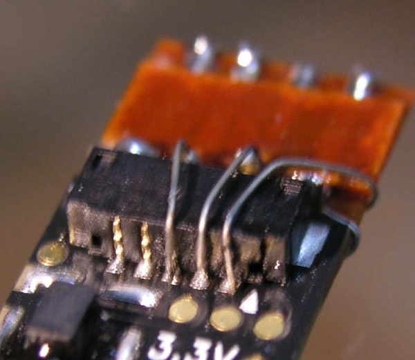
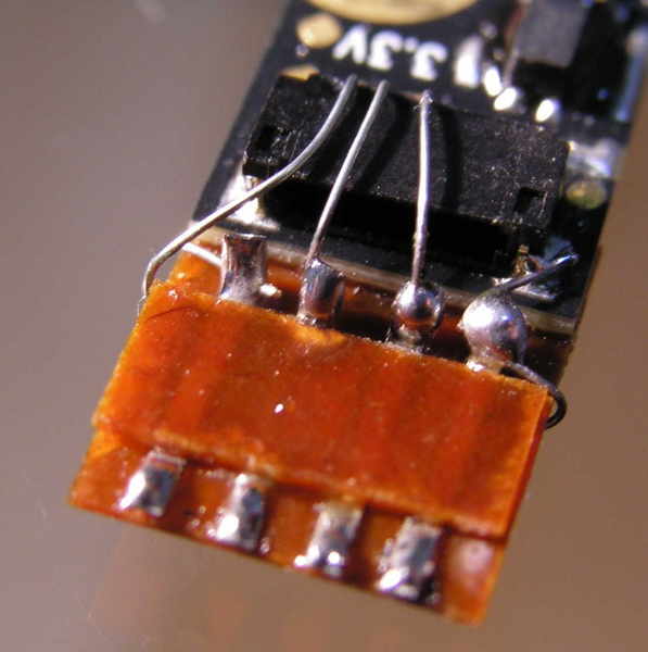
- Onto the upper side 4 very tall tin plate strips will be fixed using super glue and on top of that another even smaller piece of pcb material will be glued for stability.
- The inner side of the contact strips, the SMD parts and the plug rear contacts will be wired and soldered using small single wires from a flexible cable.
- Onto the outer side of the contact strips the wires from the USB cable will be soldered.
This way a compact, with 3.3V supplied camera module with connected USB cable can be build.
A few hints about the USB cable:
From empirical tests I found, that the maximum cable length is about three meters, where the USB cable must be of good shielded quality. With cheap USB cables intended for charging smartphones without shield, alredy 50 cm can be too llong. So don’t try to save at this point ! By the way, if you use an USB entension cable to connect the module, don’t rely on the correct standard colors (BK,RD,GN,WT). I had a experience where cables from the bay the colors were fully incorrectly used. Black was swapped with red, that resulted in a burned camera module. So better double check and measure !
Thank you for this excellent article It was very helpful and informative.
Thanks for your feedback. In case you have questions or you need further support, you are welcome to contact me.