here Part 2 of the ESP-12-in-circuit-adapter build:
- Fixing the conntact wires in the rubber pad
- Inserting the module to determine the distances
- Fixing the contact wires with hot glue
- Fixing the contact wires on the pin header side
- Fixing the angle pin header
- Glueing on the keys
Part 3:
- Soldering in the circuit wires
- Soldering in the pin headers
- Finalizing and test
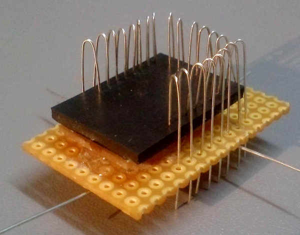
1. Fixing the contact wires in the rubber pad
Hold the contacts with small, strong compressorium pliers at the short end and push it into the first hole of the pre pinned rubber pad, so that the tip just juts out of the rubber and the long end goes through the correct hole in the bread board:
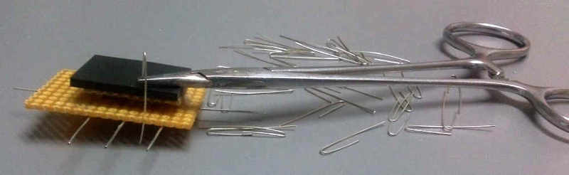
Continue with all further contacts the same way until all contacts are located in the desired position. Now adjust the height of all contacts. Slightly bent contacts need to be rectified accordingly.
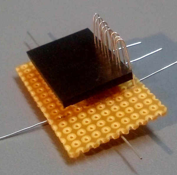
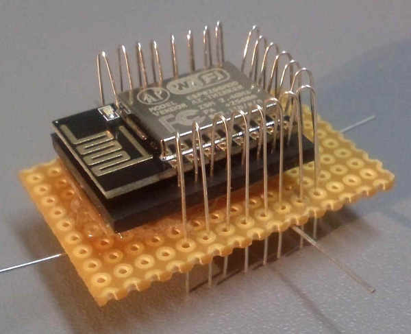
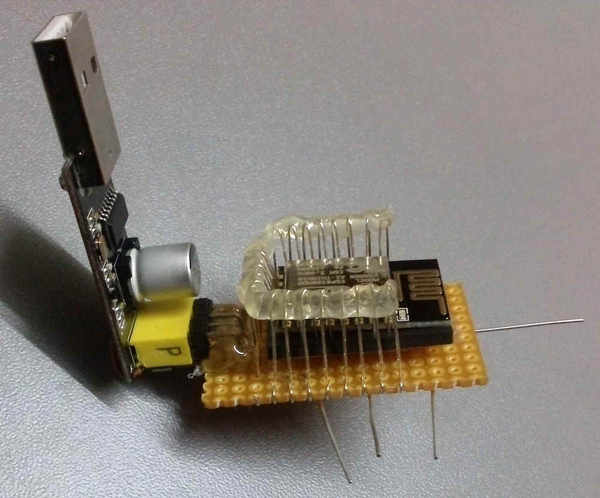
2. Inserting the module to determine the distances
Insert now the ESP-12 Module and move the contact wires carefully into the groves :
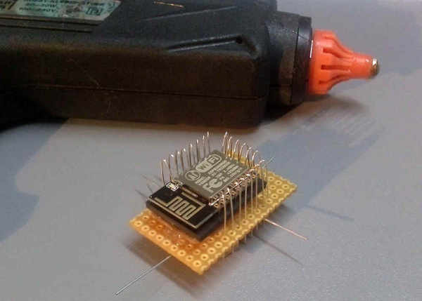
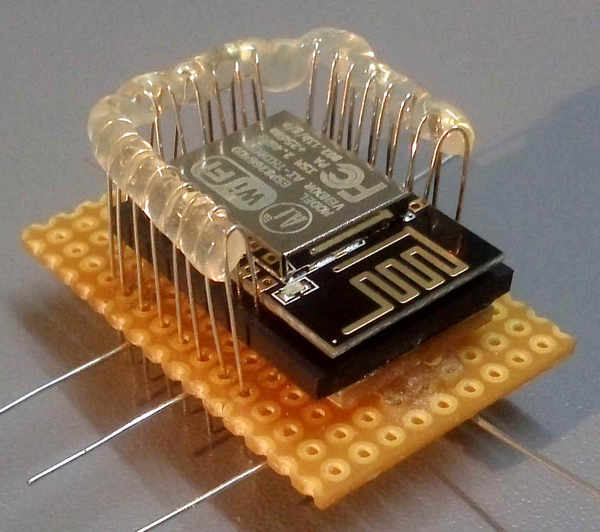
3. Fixing the contacts with hot glue
Fix the bending points with hot glue – see images:
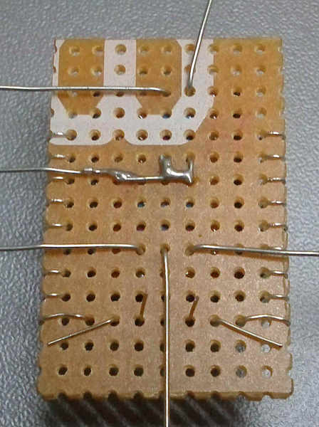
4. Fixing the contact wires on the pin header side.
Shorten the contact wires extending the base boardand bend them around the link to the neigbouring hole. Push the wire a little against the module so a slight contact pressure remains after fixing against the module:
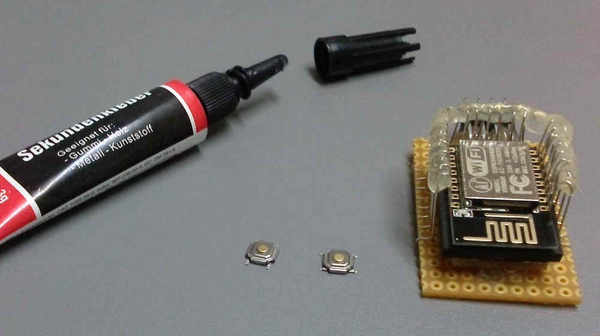
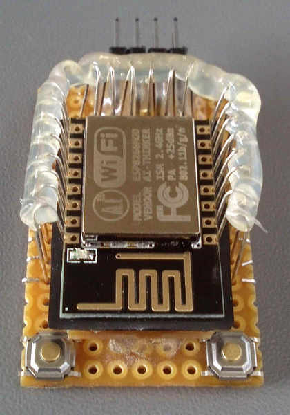
5. Fixing the angle pin header
Fix the 8-pin (or 2×4) Angle pin header onto the upper side with hot glue.
6. Glueing on the keys
Glue on the keys on the upper side as hown in the picture with a little witch glue: