
Here Part 2 of the ESP-12-in-circuit-adapter build:
- Soldering in the circuit wires
- Soldering in the pin headers
- Finalizing and test
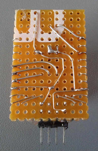
1. Soldering in the circuit wires
Solder in the lead circuit wires that are needed to operate the adapter:
2. Soldering in the pin headers
Push the pin headers onto the holes of the base board, hold straight and solder them:
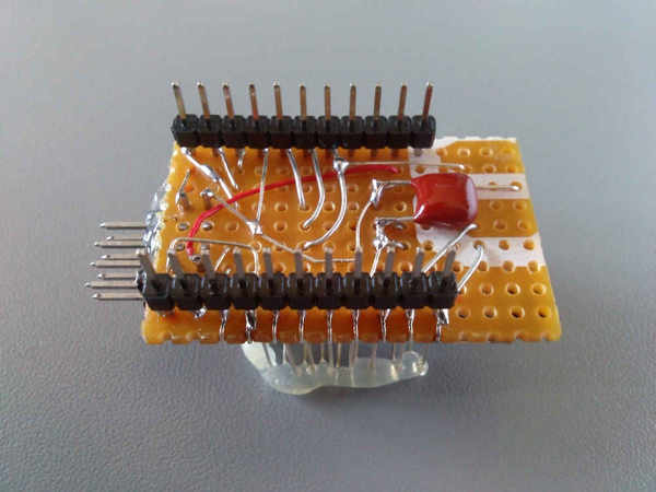
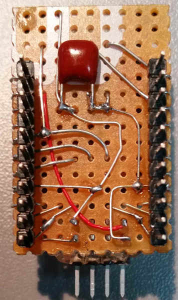
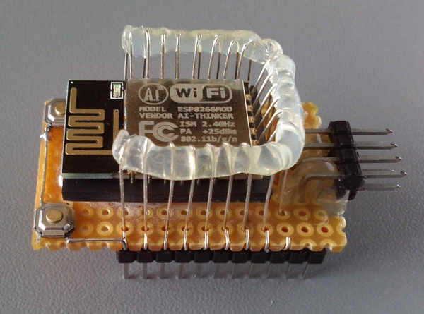
3. Finalizing and test
Complete the missing links. For the RX pin of the ESP module no space was left, so this lead was realizes using a thin litz wire. (in the image red). To operate the ESP nothing special is required. As soon as 3.3V power will be applied to the power pins, it boots from the internal flash.
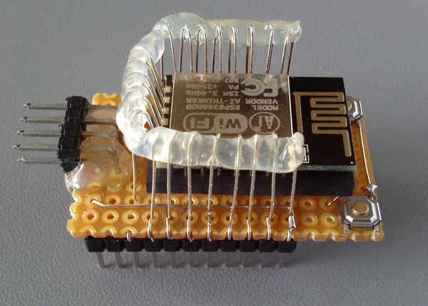
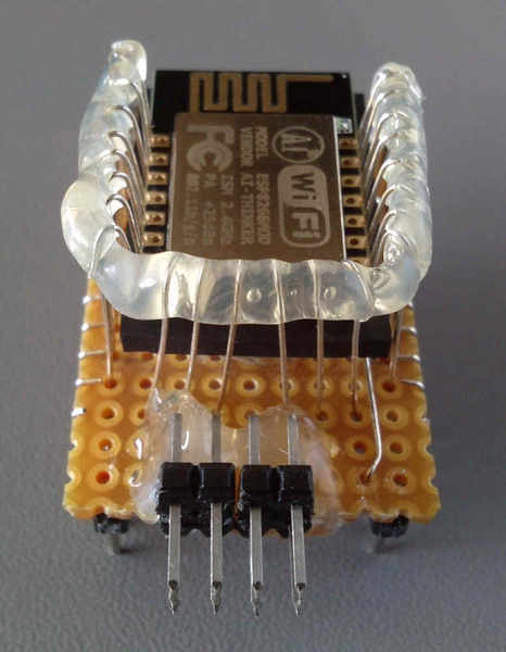
Flashing:
To flash, press both buttons then release (viewed from upper front) the right button (reset) and then the left button (GPIO0) Now the Module is in flash mode and can be supplied with programs and data.