New introduced network devices:
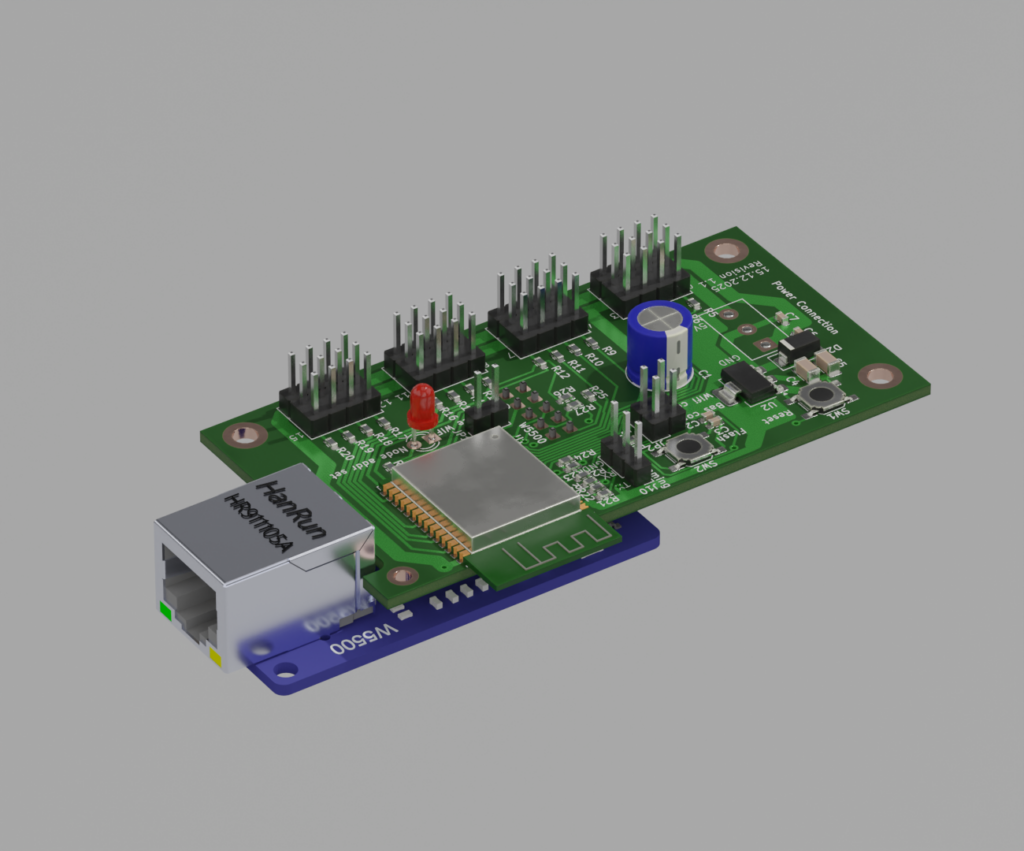
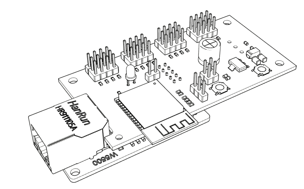
With the latest Software 3.0 the Bechele software now supports beside the existing PCA9685 PWM Boards also network devices, based on cheap ESP32 modules. Each network device may handle 16 Servos or 16 Relais or a desired mixture of both. All the data transfers from the Host (Raspi) is realized using broadcast transmissions, where all devices (nodes) receive the same data packets. According to the node configuration, the node takes the data from the packet that is intended for it. This way there is plenty of time to drive 700 Servos @ 44 ESP32 nodes, or 11000 relais @ 700 nodes with a 50ms refresh rate. Network devices may be connected via Ethernet or WiFi. Of course Ethernet driven nodes are more stable than via Wifi. The board exists in two flavours. A smaller SMD version and a larger version unsing conventional parts. For both versions you may download the gerber files and also the kicad source, so you can order a PCB from your desired PCB manufacturer. The smd version is for skilled people who know how to handle and solder SMD parts. The conventional Version uses mainly larger parts that are much easier to solder onto the PCB. Which one you use is up to you. The function is identical.
Note: Using Wifi is by far not as safe as using ethernet. To use WiFi, you need to make sure, the WiFi router is very close to the network devices, since the RSSI (Received Signal Strength Indicator) must be below 70 dB, (you may read the RSSI value during boot, when connecting a serial monitor to the TX pin of the device). Otherwise you will notice lots of missing packets – means the movement of your servos will be not continuous. Also you need an environment where there are only few other Wifi radio sources. If there is a lot of other traffic around, you will encounter the same problems. This is due to the working principle of WiFi and has nothing to do with the software. Wifi is not intended for real time control of devices ! So my recommendation is to use W5500 Ethernet modules. In a test using Ethernet with 700 configured Servos @ 50 ms refresh rate (means every 50 ms all servos got new data), none of the packets went lost over a longer time, so ethernet is quite safe.
If you do not want to build your own network nodes, you may order the ready made electronics fom PCBway.com: Therefore visit the following page and order a pcb + assembly: https://www.pcbway.com/project/shareproject/ESP32_network_node_device_for_the_Bechele_project_5e4b73b4.html
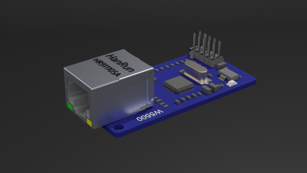
The optional W5500 adapter you may order from Aliexpress: https://de.aliexpress.com/item/1005007639330460.html
Here you can download the gerber files for the two PCB flavours:
Here you may download the Kicad Board design and schematics:
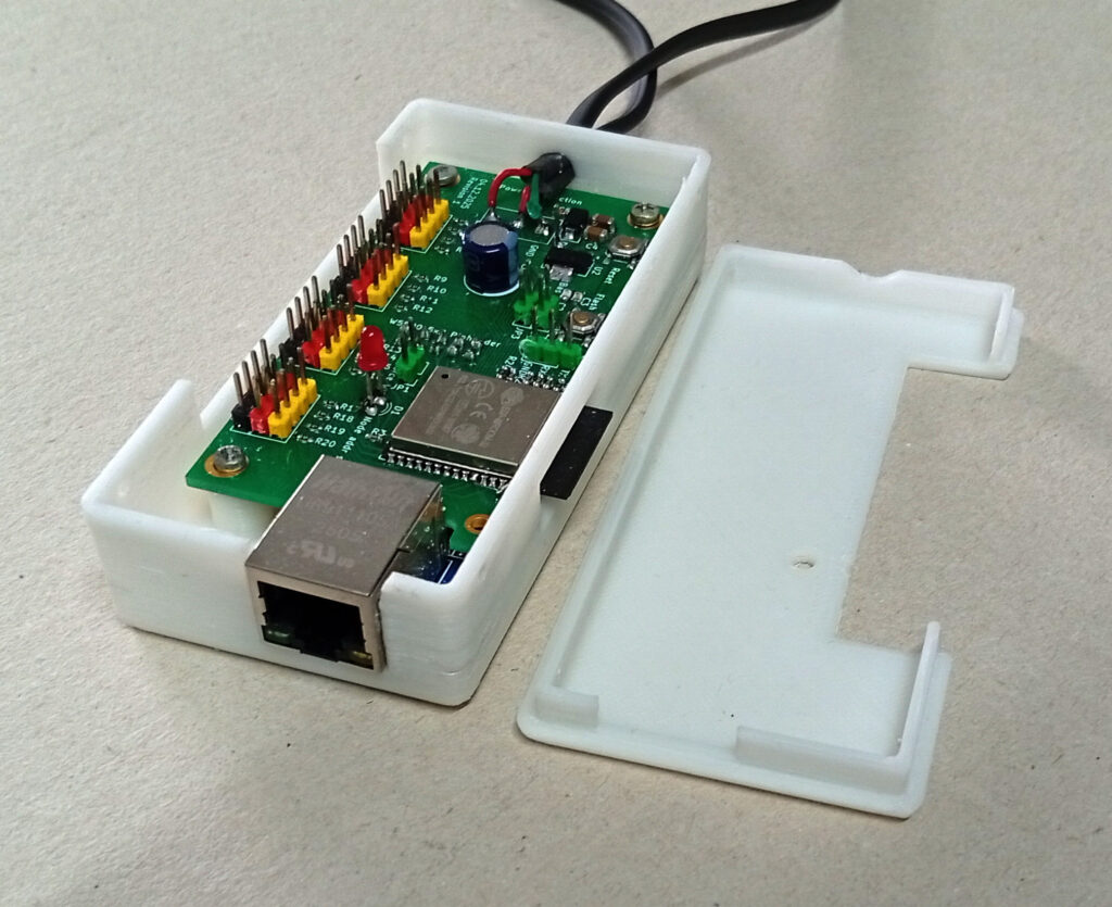
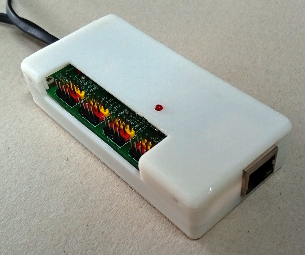
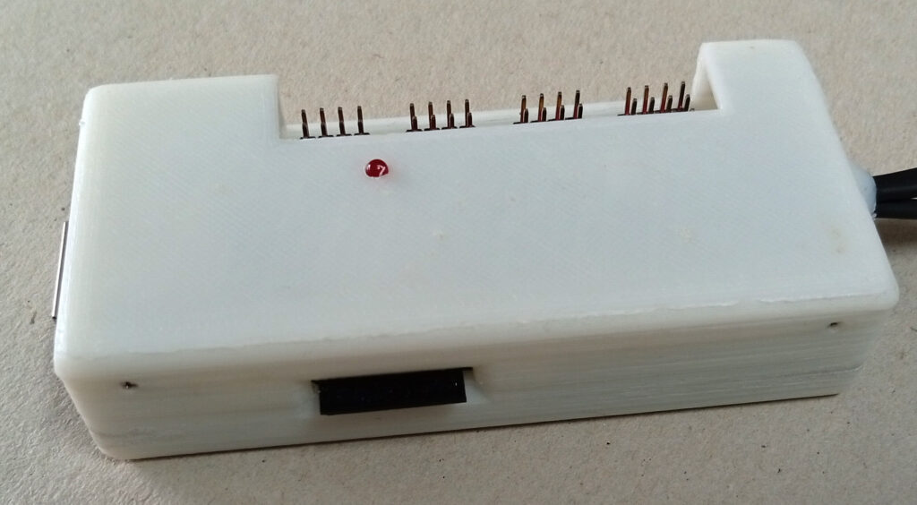
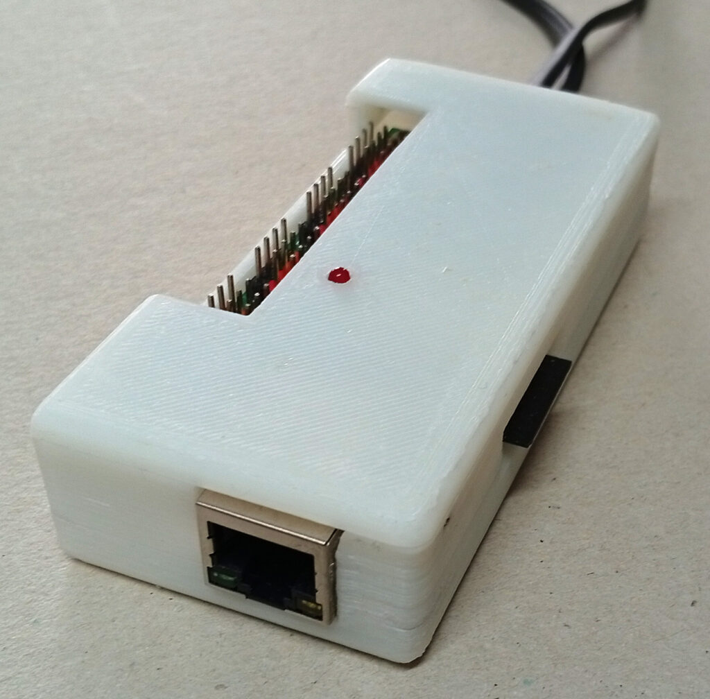
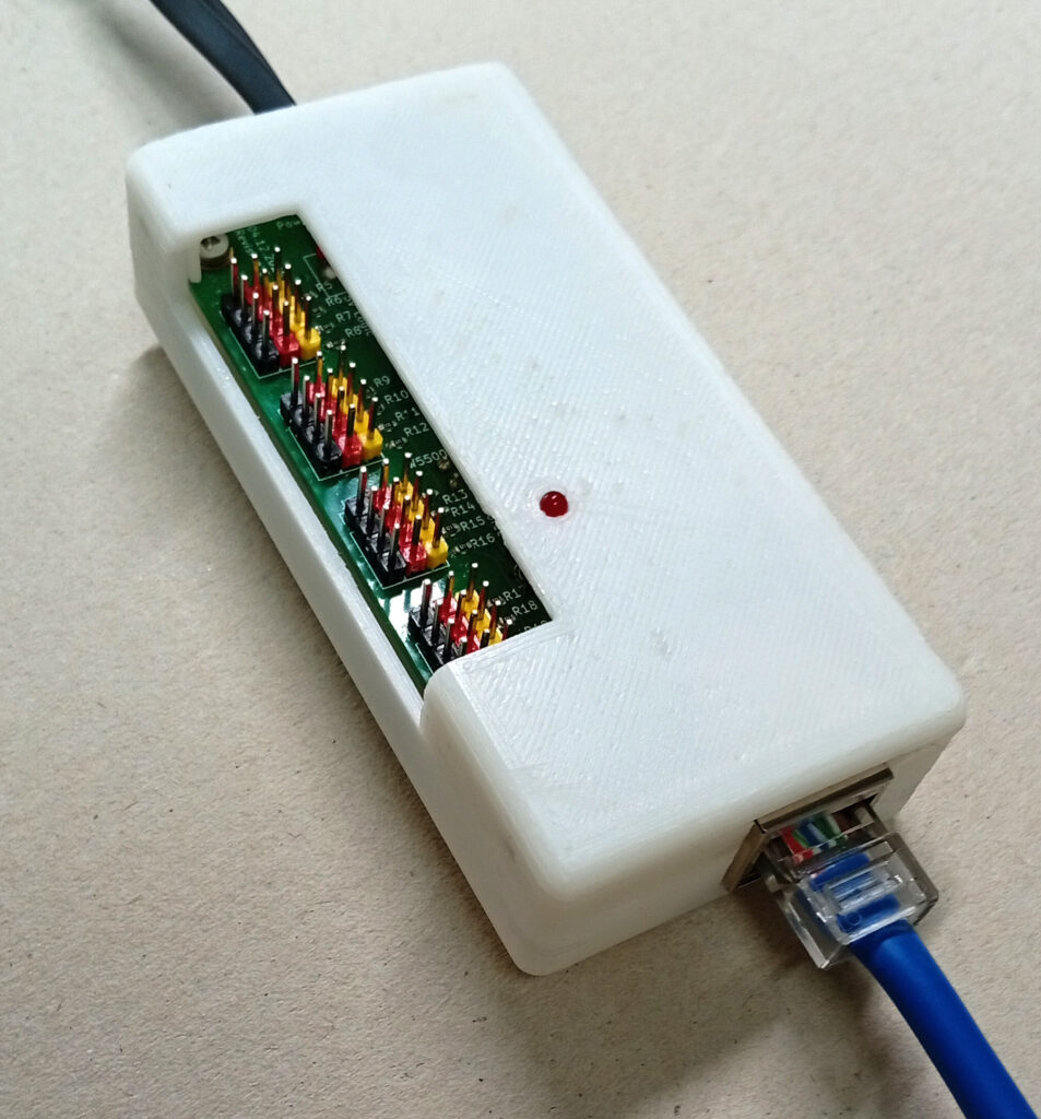
Below you will find the 3d STL data of four different electronic cases that may be used to cover the PCBs:
There is a case for the conventional PCB with W5500 Module
There is a case for the SMD PCB with W5500 Module
There is a case for the conventional PCB without W5500 Module – means just WiFi
There is a case for the SMD PCB without W5500 Module – means just WiFi
All STL and OBJ files are included in the zip:
Software description for the Bechele Project network devices.
The Arduino Firmware you may download from here: Note: You need to install the modified zip Ethernet2-W5500-ESP32.zip inside the download into the arduino library folder to be able to compile the sketch successfully. Alternatively you may download the enclosed .bin file to your ESP32Wroom32. Installation instruction you will find in the zip archive.
Features of the Bechele Network devices:
- The bechele project can use new, extremely cheap hardware, based on a ESP32 Wroom 32 or ESP32E Wroom. Furhter called nodes.
- very large installations may be easily realized using the bechele software, since Hundrets of nodes may be controlled simultaneously by the bechele software.
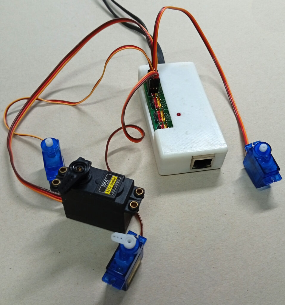
- A node has 16 output channels – means 16 Servos may be connected directly to one small hardware box.
- A node may also be used to connect binary outputs, such as relais boards
- The 16 output pins can be split into partially Servo or relais outputs in a flexible way.
- Currently approx. 32000 nodes may be addressed in one network.
- A node may have a W5500 device attached, so it gets its data via 100BaseT Ethernet.
- All nodes have built in Wifi.
- The device can be fully configured over the network, once the basic configuration has been done.
- The network traffic remains on an absolute minimum, since data is sent via broadcast to all nodes at once.
- With the limited packet length of 1432 bytes per network frame, approx 700 nodes may be controlled by the bechele software simultaneously. If more is required, the software may be adapted easily. The default 50 ms (20Hz) refresh time allows seamless servo movements without stucks or visible delays.
Description of the internal software function
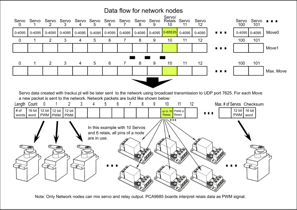
The Bechele project uses an ESP32 Wroom 32 or ESP32E Wroom as an output device in the Ethernet and WLAN network. The ESP can receive data transmitted via broadcast from the network on port 7625. The user datagram for normal operation has an indefinite length but always begins with a data word (16 bits) containing the number of transmitted user data words. The second data word contains a sequential counter, which is not initially important for the receiver. This is followed by further data words (16 bits) which, for servo data, are in the range of 0-4095 (0FFFh) and are output as PWM values to the ESP’s available PWM outputs (max. 16), depending on the configuration. For relay data, the valid value range is between 0 and 65535. A single data word can control all 16 outputs of the ESP. The outputs provide sufficient drive current to control model servos or relay modules. Depending on the software configuration, each of the 16 outputs can be operated either as a servo output with PWM or as a digital output with a constant level. Mixed operation between servo and relay outputs is also possible. The specific word in the datagram used for output is defined in configuration registers. This can be any data word in the datagram; it does not need to be synchronized to the 16 available outputs (steps), but it must be synchronized to the data word boundary. This means that the start word is specified in the configuration register in word steps, not as a byte position in the datagram. There can be multiple of these modules in the network, referred to as nodes. The maximum number of nodes in the network is set to 32765. As a result, the most significant bit in the length field of the datagram is not used for output addressing. If the length word (the first word in the datagram) contains a value greater than 32767, then the payload in the datagram is interpreted as a configuration instruction. Each node has a jumper input port (Bas conf) that is set to enable a basic configuration for the node. Nodes without the jumper set will not respond to the length value of 32768, as they are not in basic configuration mode. In basic configuration mode (with the jumper set) the sender of the broadcast will send the Ethernet address in the first six payload data words, followed by the node address and a 16-bit checksum. The ESP remembers its addresses, provided the checksum is correct, and stores them in NV memory (as an address register). The basic configuration datagram has a length of seven payload data words plus the checksum, resulting in a total length of 20 bytes. Once the ESP has received its Ethernet and node addresses, it automatically reboots when the jumper is removed. After the reboot, the new MAC and node addresses are applied. If a valid address exists in NV memory, a permanently assigned output port is set to 1. An LED connected to the node signals to the user that the address and MAC address for that node have been set. The address range for node addresses extends from 32769 (node 1) to the word boundary of 65533 (node 32765). If the first datagram word contains the node’s address (+32768), the datagram’s payload is considered the configuration for that node. Incoming configuration data is stored in 16-bit configuration data registers located in the NV data area or in the ESP’s RAM. Multiple registers can be addressed simultaneously in a configuration datagram. Starting with data word 2 (word 0 encodes the node address, and word 1 is the sequential counter), each subsequent word is considered the register address, and the following word is the register content. The number of registers in a configuration datagram is undefined. As long as the datagram does not end, any two consecutive data words are treated as a single register instruction. Both configuration data and user data are broadcast to port 7625. For later physical node identification in a configured network, the configuration program nodeconfig.pl can send a blink command (register 128) to the node address to be identified, whereupon the node’s LED blinks at a rate of 0.5 seconds. All configuration commands and PWM user data use a 16-bit checksum.
The following registers in the NV memory are occupied:
Registers 0-5: Ethernet address of the node.
6: Node address.
7: Number of PWM outputs.
8: Start word in the payload datagram (equal to the servo number in the operating program) containing the payload data applicable to this node.
9: Pin number to which the PWM start word is output. All subsequent PWM data words are output to the following pins until the number (7:) is reached.
10: Number of output pins reserved for relays.
11: Data word in the payload datagram (servo number) containing the bit data for the output pins, where 16 bits represent 16 outputs.
12: Pin number to which the first bit in the payload data word is mapped.
The following registers in RAM are active:
Register 128: Blinking active
Register 129: Blinking duration in seconds - currently unused by the configuration software.
Register 130: Node reset - as soon as this register is set to 1, the ESP performs a reboot.
Register 131: Status report to host via UDP (unicast) on port 7626.
Register 132: Unconfig Node - if this register is set to 1, all registers are set to the default value 0 and a reboot is performed. This means the box will then be in its factory default state and must undergo a basic and node configuration before use.
Two additional commands exist that are executed by all nodes on the network.
- 65535 in the datagram’s length word: Deactivates all PWM outputs. This is usually issued after a session ends to protect the servos.
- 65534 in the datagram’s length word: Restarts all nodes.
Hardware:
A W5500 network adapter may be connected. If it is detected, it is initialized and Wi-Fi is disabled. If initialization fails, the node will still wait for a network connection via Ethernet – meaning there is no fallback to Wi-Fi. If the node should use Wi-Fi, the “force Wi-Fi” jumper can be removed – this step requires a reboot. The ESP obtains its IP network address via DHCP. In Ethernet mode, the ESP does not respond to unicast packets. The only communication with the ESP occurs via broadcasts on port 7625. Therefore, a network ping provides no information about the node’s functionality. The initial Ethernet address is set to DE:AD:BE:EF:00:01 in basic configuration mode (Bas Conf Jumper). This means that each module must be initialized separately, one after the other; otherwise, the same Ethernet address will be assigned to two or more nodes during basic configuration.
Configuration procedure for Ethernet and Wi-Fi (after basic Wi-Fi configuration):
1. Set the Basic Config jumper.
2. Reset the node using the reset button on the board.
3. Set the node address in the configuration program nodeconfig.pl - the Ethernet address will be assigned automatically.
4. Press the Basic Config button in the configuration program.
5. Remove the Basic Config jumper from the node. This will automatically reboot the node. After a few seconds, the LED on the node should light up. This indicates that the basic configuration was successful.
6. Select the node address that was just set - if it is not already active - and use the "Get_Node_Status" button to display the node's configuration. If OK, you can proceed to step 7.
7. Set the remaining configuration parameters, which are usually different for each node.
8. Press the "Send_Node_Setup" button - the remaining parameters will be set. If the associated automatic check is successful, the configuration for this node is marked as "confirmed" in the database used by nodeconfig.pl.
9. The node is then ready to receive and output PWM and binary data. No further configuration is required after switching the node off and on again.
Configuration procedure for Wi-Fi:
Note: The jumper "0= force wifi" must not be set:
1. Activate the Wi-Fi manager via the "Wifi Conf" jumper.
2. Reset the node using the reset button on the board.
3. Select the access point "ESP32_PWM_Node" on the host (smartphone or computer).
4. The Wi-Fi manager will start automatically, depending on the device.
5. Configure the Wi-Fi network (SSID and Wi-Fi password).
6. Save and remove the "Wifi Conf" jumper.
7. Now proceed with the basic configuration as described in the configuration procedure.
Summary in brief:
Datagram description Basic configuration when length word = 32768:
1st word (0) in the datagram = Length word
2nd word (1) in the datagram = Sequential number
3rd word (2) in the datagram = MAC 1 - Register -> 0
4th word (3) MAC 2 - Register -> 1
5th word (4) MAC 3 - Register -> 2
6th word (5) MAC 4 - Register -> 3
7th word (6) MAC 5 - Register -> 4
8th word (7) MAC 6 - Register -> 5
9th word (8) Node address -> 6
10th word (9) CRC checksum
Total length of a basic configuration command = 20 bytes
Datagram description for Configuration mode when length word > 32768:
1. Word (0) in the datagram = Length word (over 32768 (8000H 32769 to 65533))
2. Word (1) in the datagram = Sequential number
3. Word (2) Register number to be set
4. Word (3) Register content
5. Word (4) Register number to be set (Optional if multiple registers are to be set)
6. Word (5) Register content (Optional)
..
..
Last word = CRC checksum
Calculation of the node address from the length word: Node address = Length word – 32768 (received on ESP side), Node address = Node + 32768 (send from host side) Range 1-32765 (32765 nodes maximum)
Datagram description in payload mode: if length word < 32768:
1st word (0) in the datagram = Length word less than 32768 (8000H) 2nd word (1) in the datagram = Sequential number 3rd word (2) up to -> 32767 = Normal PWM and relay data .. .. Last word = CRC checksum
Registers 0-127 are NV (permanent) Register:
6: Node address
7: Number of active PWM pins (0-16)
8: Servo number assigned to the first configured pin. All subsequent servo data is assigned to the following pins until the number of pins is exhausted.
9: Pin number to which the servo number in 8 is mapped
10: Number of active relay pins (0-16)
11: Servo number containing the relay bit data
12: Pin number to which the first relay bit is mapped. (A word contains 16 bits - each bit can define a digital output, bits 0-15). If the pin number is not zero, the bit data is shifted accordingly.
Registers 128 to 255 are RAM registers:
129 Blink duration - currently not used by the configuration program
130 If set, a targeted reboot of the node is performed
131 Status report to host via unicast UDP (0x0001 as configuration date) to the server host. This register is cleared (00) after a single execution, meaning the host must poll for status updates.
132 Reset node to default values - this means it must be completely    reconfigured. Only the Wi-Fi configuration remains.
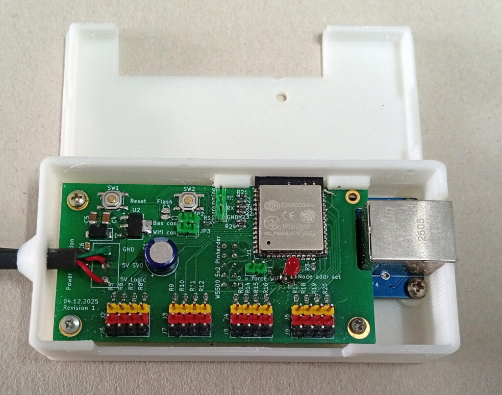
Jumper functions:
Jumper WIFI Conf: -> starts the Wi-Fi Manager web interface to set the SSID and password
Jumper Bas.Conf: -> puts the node into Basic config mode, where it may take a Node Address and its Ethernet Address. By removing the jumper once it has got its Addresses, the node will reboot automatically. !!! Only one Node in the network at a time may have the Bas.Conf jumper set !!! If you disregard this, you mess up your network !
Jumper 0=force Wi-Fi: -> if removed, or if no W5500 board is present, Wi-Fi is used. Note: Wifi needs a high signal strength (RSSI < -70 dB), otherwise you will encounter lots of lost packets - Means you servos will not run smooth.
FYI:
A problem arises with mixed PWM and binary outputs: While the output start positions can be freely defined, the number of outputs must match the pin boundaries. If the pin boundaries are misconfigured, the configuration program nodeconfig.pl will issue warning messages. However, the program cannot verify which data will be servo or relay data, nor can it check if these are correctly assigned, because the data in the datagram is the same for both relays and servos. (1 word per PWM value, and 1 word = 16 bits = max. 16 relay pins). This means the user must ensure the correct start words are configured. Otherwise, PWM values may be interpreted as binary values for digital port outputs, or vice versa. Example: Number of PWM outputs: 12 (12 words); Number of binary outputs: 4 (1 word); PWM start position: 20 – ranges to 31. If binary outputs are located in between – for example, relay start 24 – then the binary and PWM values will overlap. This means the binary data is output as PWM to the 5th servo. The binary outputs would be correctly displayed in this case. We have to accept this. The advantage of the flexible start position determination, and thus the distribution between servo and relay outputs, lies in the fact that some nodes only have to control a few servos, while others control the entire number. This means the host software doesn’t have to strictly adhere to node boundaries; instead, logically related servo and relay ranges can be created sequentially. Which node controls which function is determined during node configuration. Incidentally, the start positions (servos/relays) in the datagram for a node don’t have to be adjacent. If desired, all servos for all nodes can be placed at the beginning of the datagram and all relays at the end, or vice versa. What doesn’t work is having two or more servo or relay ranges per node, because only one configuration set exists per node.
Below you can see Datagram structure of the broadcast data transferred from the Raspi to all nodes: