
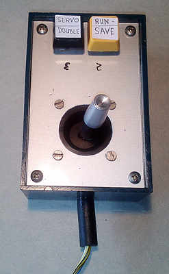
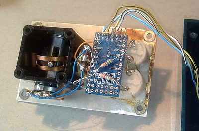
The self made joy stick as an input device and its wiring
The joy Stich to record the servo movement syncronous to the sound is realized using an arduino.
The wiring diagram can be downloaded using the link below:
Here the software of the joy stick for downloading:
Alternatively to the serial joystick, you may use also the following alternative if you prefer to use a USB HID device joystick: USB HID Joystick
The Arduino source code for the joy stick
or using drag and drop:
 // These constants won't change.  They're used to give names
// to the pins used:
const int analogInPin = A0;   // Analog input pin that the potentiometer is attached to
const int analogInPin2 = A1 ; // Analog output pin that the LED is attached to
const int Button1 = 2 ;
const int Button2 = 8 ;
int AsensorValue1 = 512;         // value read from the pot
int AsensorValue2 = 512;         // value read from the pot
int inByte = 0;               // incoming serial byte

void setup() {
  // initialize serial communications at 9600 bps:
  Serial.begin(38400);
}

void loop() {
  // read the analog in value:
  AsensorValue1 = (AsensorValue1/10*9+analogRead(analogInPin)/10);     // Mittelwertberechnung
  AsensorValue2 = (AsensorValue2/10*9+analogRead(analogInPin2)/10);    // schleichend
  int button1State = digitalRead(Button1);
  int button2State = digitalRead(Button2);
  if (Serial.available() > 0) {
  inByte = Serial.read();
    if (inByte == 52) {
      // print the results to the serial monitor:
      Serial.print(AsensorValue1-50);
      Serial.print(" ");
      Serial.print(AsensorValue2-110);
      Serial.print(" ");
      Serial.print(button1State);
      Serial.print(" ");
      Serial.println(button2State);
    }
  inByte = 0;
  }
}
Is there any chance you would be willing to modify the software to allow for the use of a 3-axis joystick? It’s a joystick that also rotates alongside a button in the center (mine is P/N: JH-D400X-R4-10K), so it allows for the performing of more inputs at once. I am going to try to use this project “live” for a large majority of what I’m doing, I’d also kill to have the option to have say 6 buttons that could be set up to perform often used movements like blinking, eyes rolling with eyelid closing, eyes crossing with associated facial expressions, etc. It would be rad if we could record mini facial actions for all 6 buttons to be called back just that easy. I’d be willing to pay for your time if you’re interested. Not about to try to demand major changes without supporting the project haha.
Dear Blake, first of all thanks for your questions. I agree, sometimes it would be nice to have more parallel input channels than just two. With the working principle of assigning any servo to a joy stick movement it would be possible to add a third axis to the software without a huge change. However, the button idea would blast the space available on the screen, so a different working principle would be necessary. Currently I am thinking of adding a module to input data from face recognition software and assign it to servo movements, but this is just a raw idea, what I could do in the future. In any case that will last quite some time until a working program is ready. Currently I am re-building my house and I am still very busy with this project. By the way, I am not interested in gaining money out of my activities, so If I do some changes, I will do it for free anyway.