
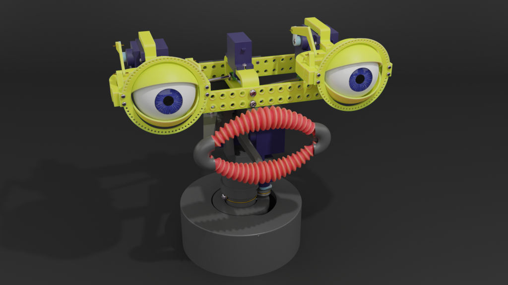
This puppet head I designed to show the possibilities of the bechele 3 Software (V2.0) Actually I did not plan to publish this, but people asked for it, so I decided to publish it also.
The Puppet head consists of two parts:
- The eye mechanism, that I already publishes earlier: https://bechele.de/?p=814
- The following parts zip that I call “neck” as a unit – it consists of all the required stl files along with stp file for those who want to import the head in a cad program:
Here you may see the head(s) in action:
Here a Bill of Materials needed:
Tools required:
Drill 1.5 mm – to calibrate the servo screw core holes.
Drill 1.2 mm – to calibrate the core holes for the M1.6 threads
Drill 2.4 mm – to calibrate the core holes for the M3 threads
Drill 3 mm – to calibrate the 3mm pin and axis holes
Drill 3.2 mm – to calibrate some M3 screw holes
(see the images at the end of the gallery for details)
Thread Tab M3 and M1.6
(see the images at the end of the gallery for details)
Set of small metal files.
Small painting brush to apply some seperation wax onto the lip core
Small painting brush to apply latex milk onto the lip core
Parts needed:
Cyan Acrylate Glue
Some liquid wax to apply onto the lip core.
Latex milk to create the lips.
5 Servos SG90 preferrable with slanted cable outlet like from sunbird.
3 Screws M3 x 12 DIN7985 (ISO7045)
5 Screws M3 x 10 DIN7985 (ISO7045)
1 Screw M3 x 6 DIN7985 (ISO7045)
10 Screws M1.6 x 5 DIN7985 (ISO7045)
All servo screws delivered with SG90
2 additional servo mounting screws
1 long servo horn mounting screw
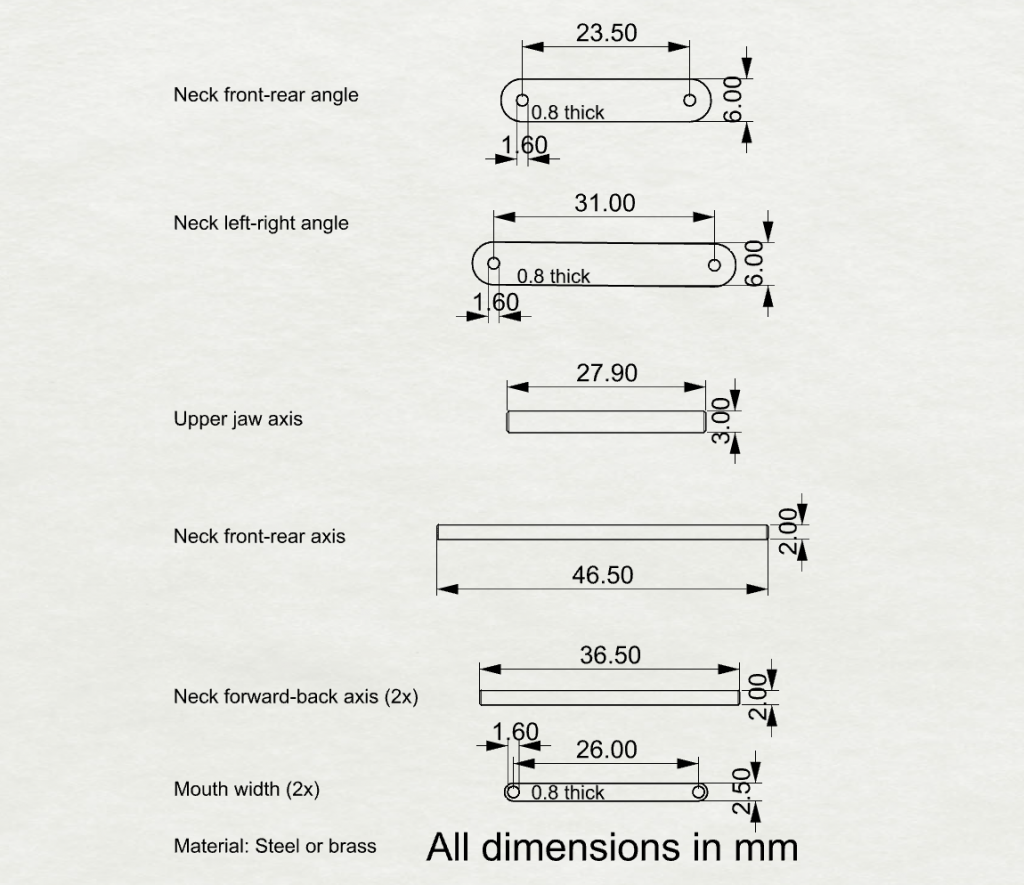
Steel or brass pins as shown in the pin drawing at the end of the image gallery.
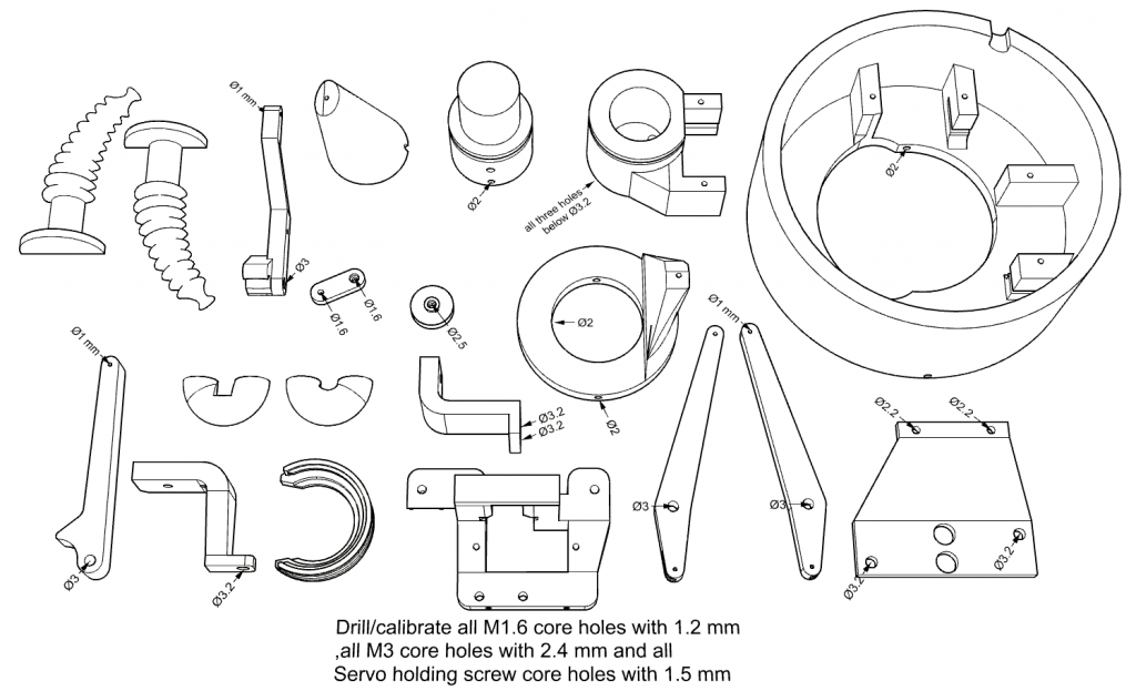
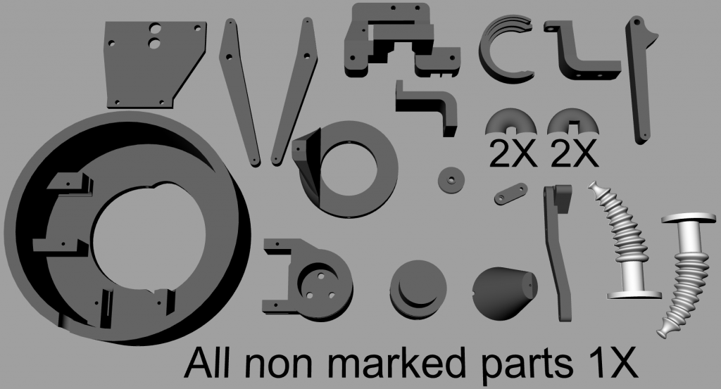
Preparation of the printed parts:
All holes need to be calibrated according to the images shown at the end of the gallery.
Also parts that are intended to fit together need to be re-worked at the fitting areas with a metal file to get a close, but easy moving fit. If fittings become too lose, the mechanics will not work properly. If fittings are still going too hard, it has the same effect. In other words, precision is very important.
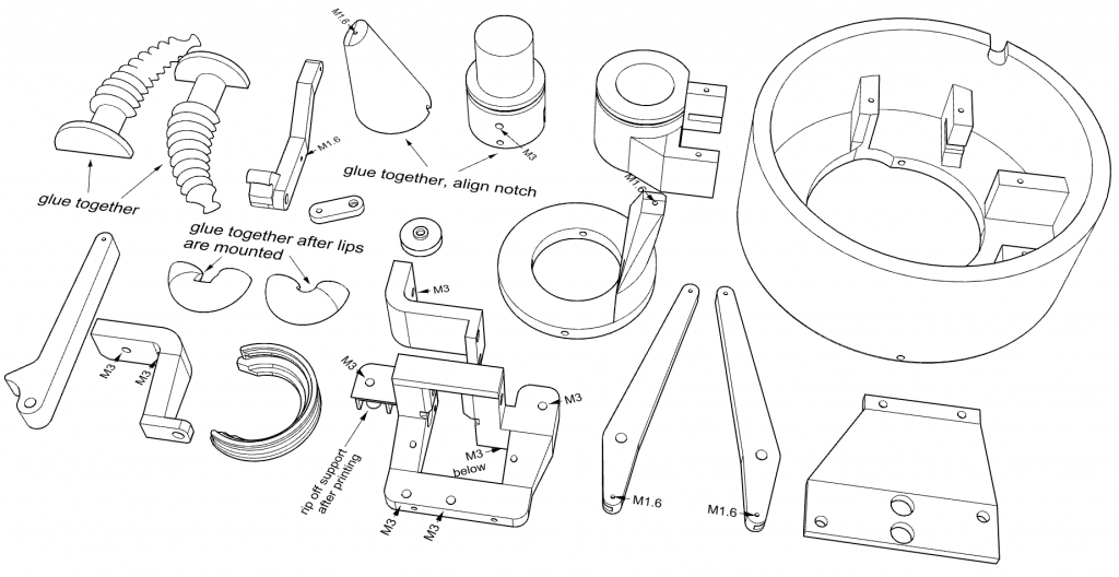
Here you can see what kind of holes need to be calibrated and what kind of threads need to be cut. Also you see the number of parts to print and which pins and levers you need in addition.
If you want to asee where the parts are mounted, have look at this video:
Can you provide a direct circuit connection diagram of the circuit board
Hello, The main wiring shows how to connect the wires: https://bechele.de/?page_id=199
Also this video may help: https://www.youtube.com/watch?v=I9sBTcGVVRQ
If you have a specific question, you are welcome to contact me.