
Very precise Joystick
To understand the focus of the project, I recommend the following overview video:
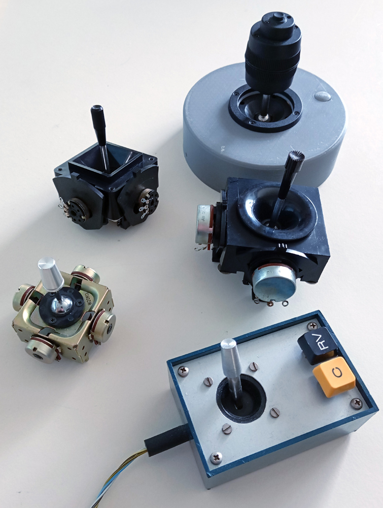
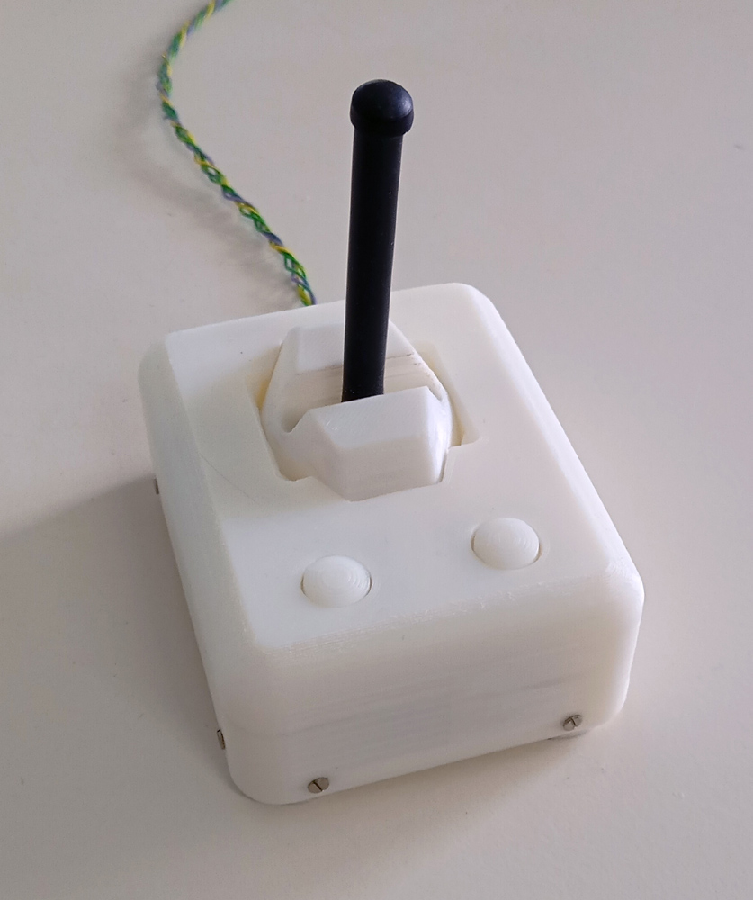
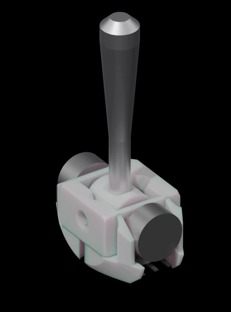
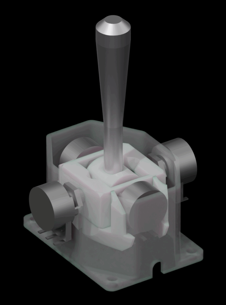
This project describes a very precise 3D printable mechanical joystick, based on potentiometers. I tried to use existing joysticks in conjunction with my bechele project, that allows to bring puppets and models electrically to life, but I was disappointed about the accuracy of existing joysticks on the market, so I decided to build my own. Ordinary potentiometer based Joysticks use some transmission mechanics to couple the stick movement with the potentiometer rotation. Nearly all designs do this on cost of a slight mechanical inaccuracy, that causes a inconsistency in the relation of the stick position and the resulting potentiometer resistance. Typically moving the stick from differnt directions to the same mechanical point results in slightly different resistance values. The design of this Joystick overcomes these restrictions nearly fully, since only the inaccuracies of the potentiometers themselves define the inconsistency. The accuray will be achieved using the bearings of the potentiometer as the rotation points. Each axis uses two potentiometers that are connected electrically antiparallel. This way, the output voltage of the voltage divider can be used with the full range from 0 to full voltage. That means the resolution of the levers full movement range may coincide with the full range of the A/D converter that digitizes the signals. In reality the joystick is very sensitive and the repeat accuracy is very good.
Required Tools
Drill 6 mm
Drill 7 mm
Drill 2.4 mm for the M3 core hole
Drill 1.6 mm for the M2 core hole
Drill 3.2 mm for the M4 core hole
Thread taps M2, M3, M4
Screw driver for the two m4 worm screws
Screw driver for the 8 M2x5 Cover screws
Screw driver for the two M3 x 12 screws
10 mm fork wrench of 2.5 mm thickness max.
All 3 D printed parts from the zip file
1 x Buttonstand
1 x Cover
1 x cover_bottom
1 x hood_rotation
1 x Joystick_base
1 x joystick_coupling
1 x Joystick_frame
1 x y-stop
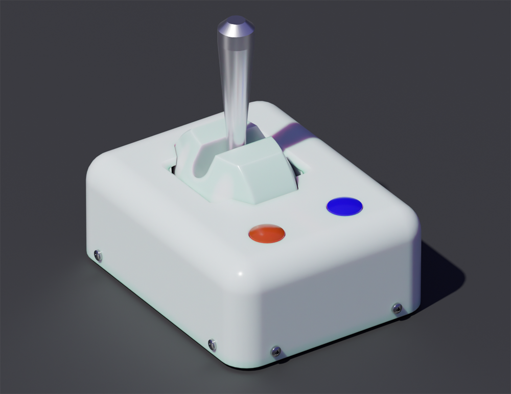
1 x Joystick_stick – however you may also find an alternative lever according to your needs
2 x Button
1 x mounting helper bolt
Bill of material (BOM)
8 Screws DIN 7985 M2 x 5
2 Screws DIN 7985 M3 x 12
2 screws DIN 551 M4 x 5
1 Screw M4 x 6 with 7mm diameter head as a mounting guide
1 mounting helper screw M3 or Pin 3mm
4 Potentiometers 10 KOhm Type WH148 or RK097 of good quality. Make sure there is no play in between axis and slider of the potentiometer
2 Momentary Type Tactile Push Button Switch 4 Pin SMD 4*4*1.5 mm
Cyan acrylate glue (super glue)
Sticky tape
Eventually thread rod M4 of 55mm length
Very flexible single wire flex cable for the X-Potentiometer wiring Red, Black and Yellow 0.13mm²
5 cable ties 3mm
Post processing after printing
Some post processing may be required after printing all 3D .stl files from the zip
- All parts are designed in a way, that there is no need for printing supports
- If you printing added brims you need to clean off them for further processing
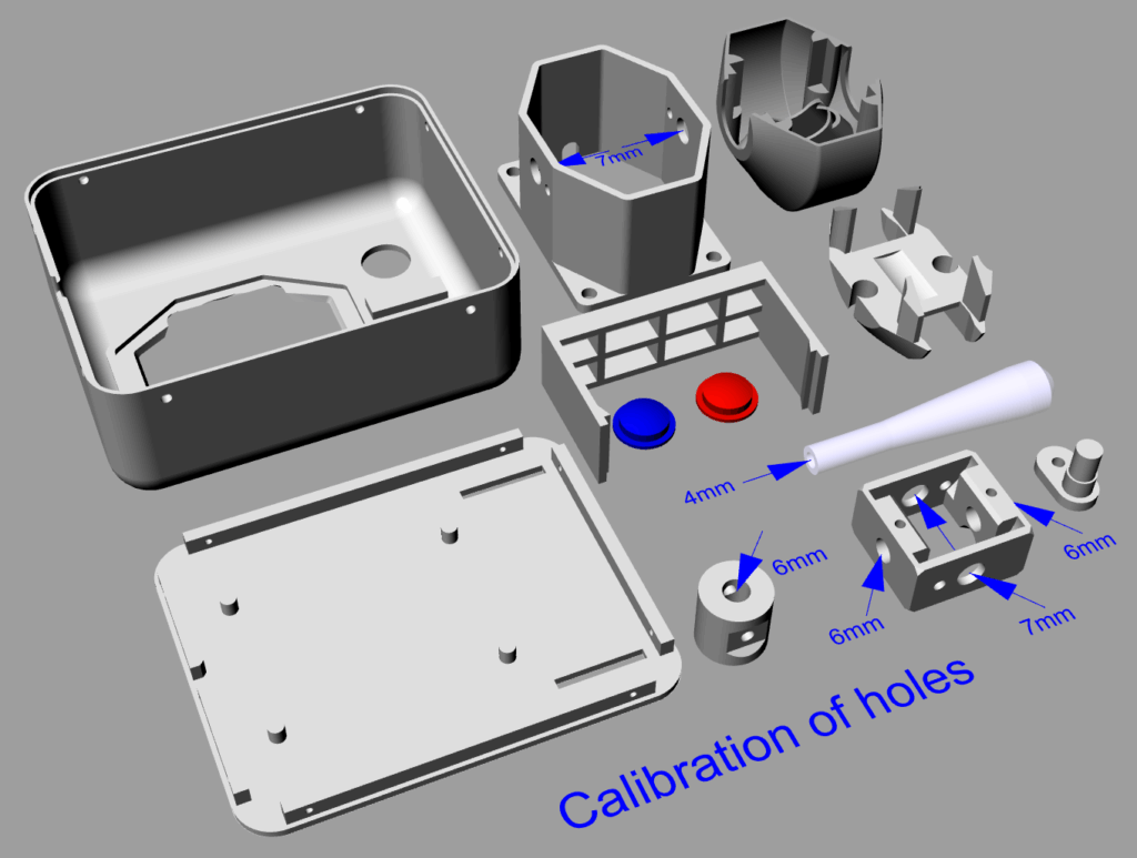
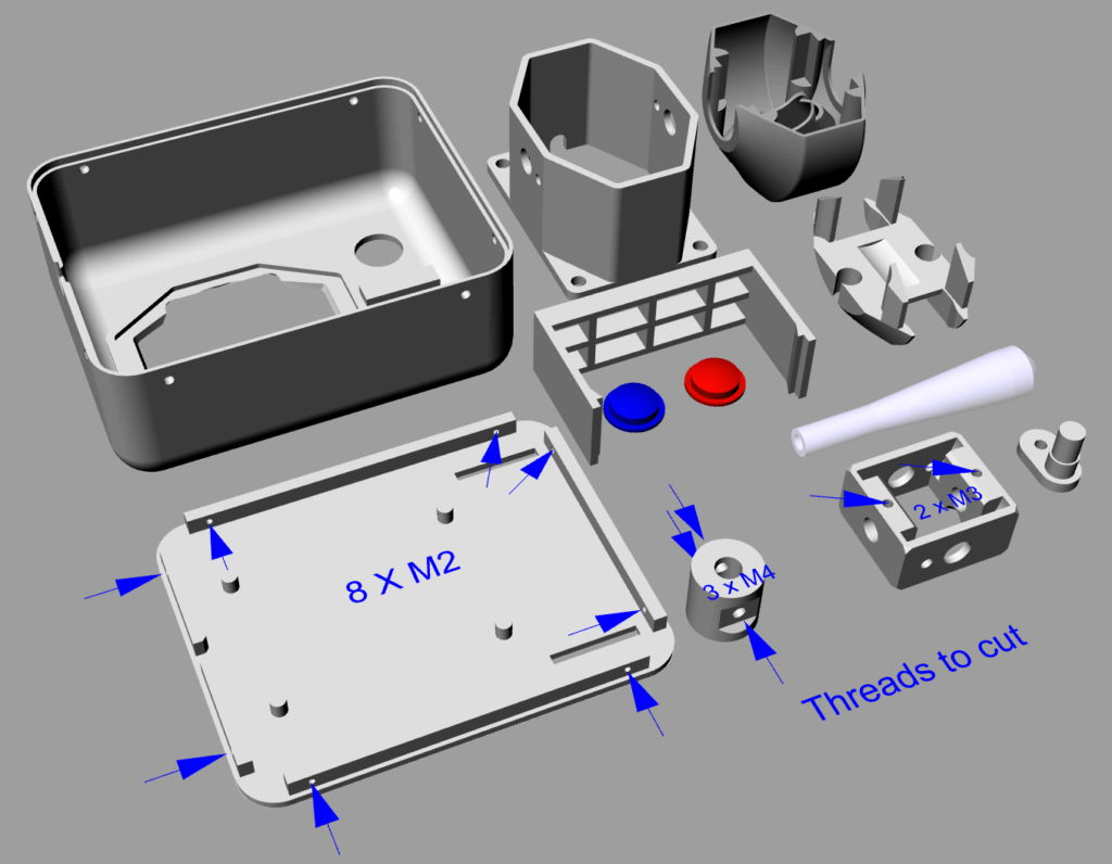
- In order to cut threads, I recommend to calibrate the core holes using a drill : 1.6 mm for M2 2.4 mm for M3 and 3.2mm for M4
- Calibrate the marked holes as indicated in the image
- cut the threads as indicated in the image
Mounting and Adjusting
- Mount and adjust the X-and Y-Axis as explained in the video:
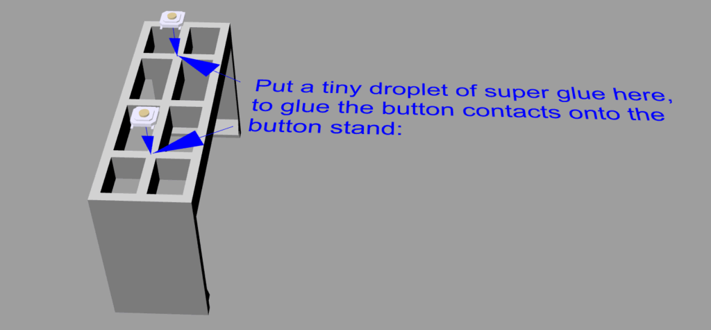
- Glue the two micro push buttons onto the part Button_stand as shown in the image
- Install the rest of the parts as explained in the video
Electronics installation
The Joystick was first intended to be used in conjunction with the bechele project, but it can be used also as a ordinary joystick for other purposes. Therefore the electronics is depending on the application.
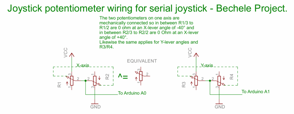
The general wiring of the joystick potentiometers are always as shown in the image: Note that the combination of two potentiometers are equivalent to a single potentiometer, with the advantage, that if it is used as a voltage divider, the voltage range can be adjusted by the mounting angles inside the joystick. The overall resistance in between VCC and Ground connection varies with the adjustment, but this is pretty unimportant for a voltage divider as long as the power dissipation does not exceed the limits of the potentiometers. With an angle range of +/-40° the resistance is around 6 to 7 KOhm and therefore far beyond the limits for a low voltage.
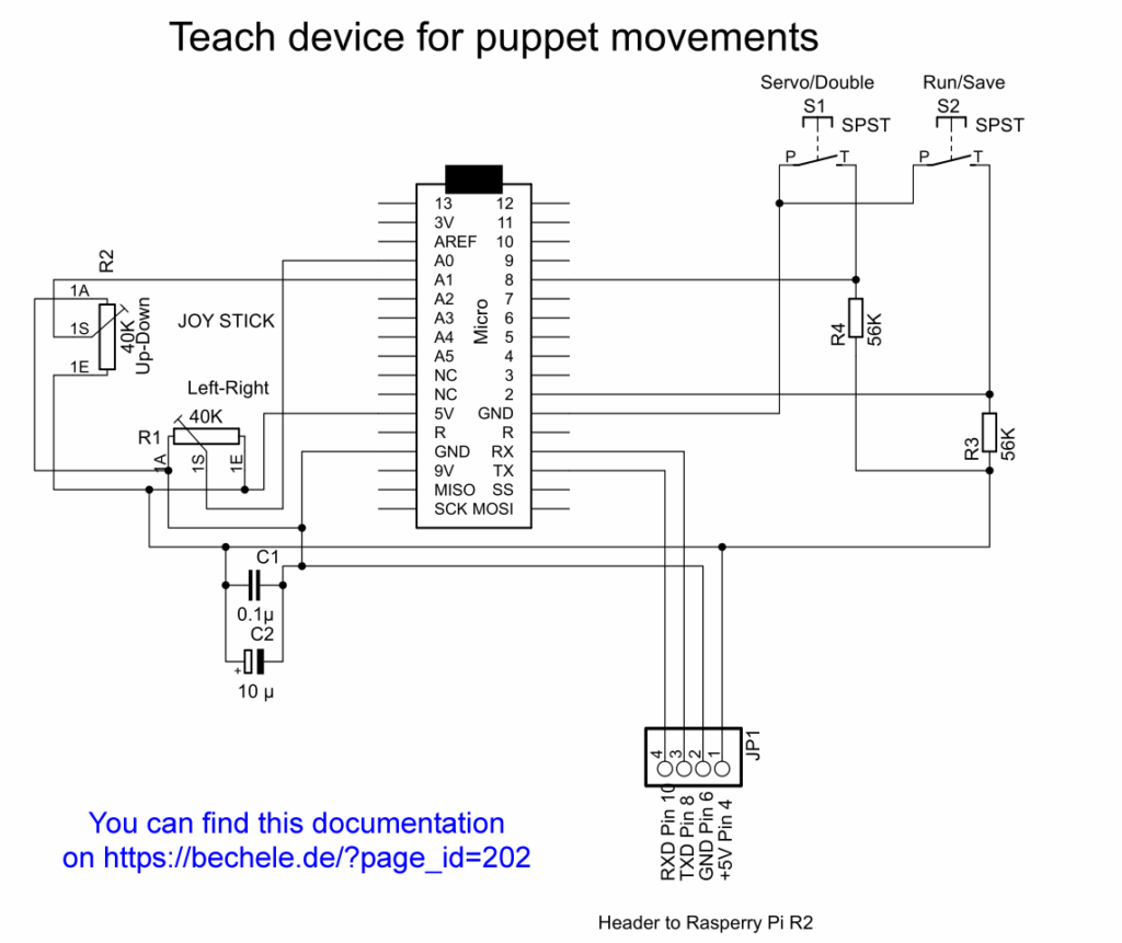
For the bechele project you may use the arduino circuit – just replace the potentiometers as shown in the equivalent see https://bechele.de/?page_id=202 for more
If you want to use the joystick mechanics as an ordinary HID joystick device you may check for the following project: https://gp2040-ce.info/
Trouble handling
If you run into trouble with any part of the design, first check, if you checked the documentation first, but if after that you cannot get ahead, please get in contact with me and I will try to help you.