
Summary:
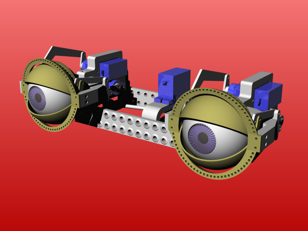
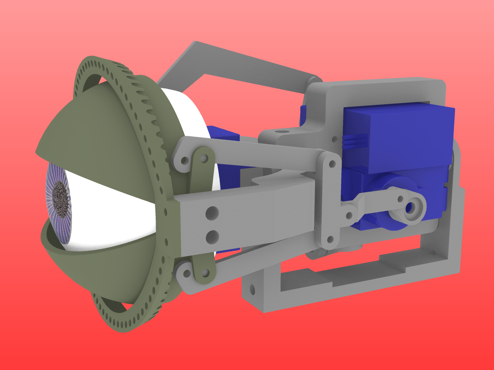
The adaptable eye mechanics is born out of the bechele project. It is a better and easier eye mechanics than the one shown in the bechele project
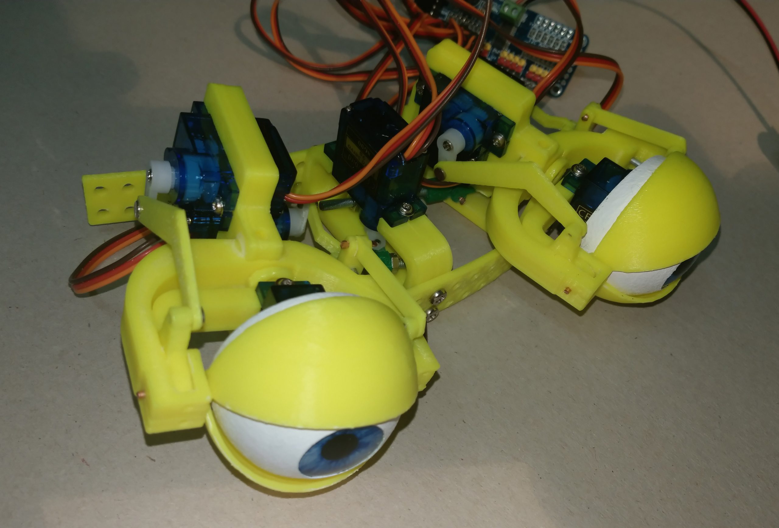
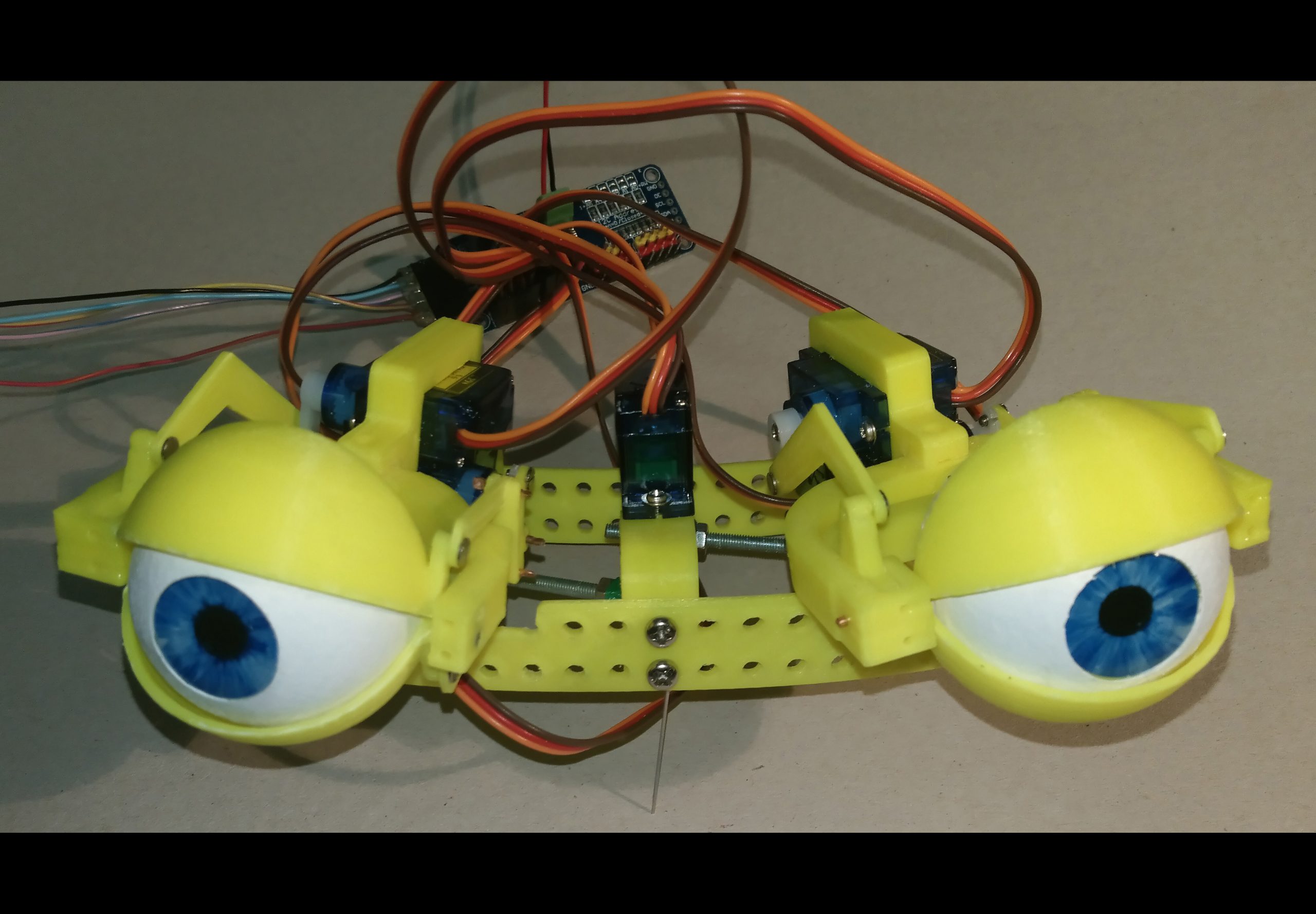
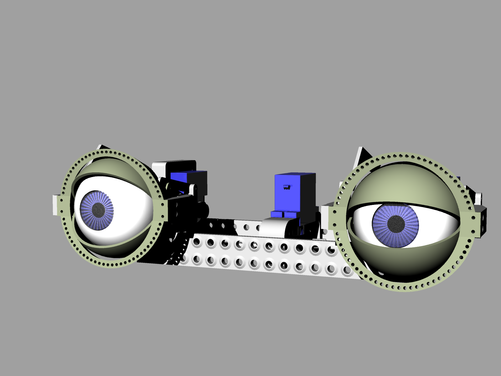
This Project is an extension of Thing https://www.thingiverse.com/thing:2781756. It uses many parts of my first 3d printable eye mechanics, but now eye distance and eye angle are adjustable in steps. Also single eyes are possible.
See the following video to see the thing in action: https://makertube.net/w/wW775VPPxZ1a6aT2aupfCH
This video shows how to mount the eye mechanics in detail https://makertube.net/w/b2kSypkuHn2pyXhfs6ThNE
This how to setup the hardware: https://makertube.net/w/n6LdjZEPqVUqzqY2tDZe3b
This how to operate the software: https://makertube.net/w/1okjia1dZsw7kVeKooS3uH
See here what the thing is actually intended for: https://makertube.net/w/a9fvFKMVXRibykitEppDQQ
See https://bechele.de/?page_id=70 to see the electronic hard and software for this thing.
Update at Jan.1.2020: Updated hinge frame that does not require filing to achieve the maximum eye angle
Here you may download all 3D printable parts in a zip file:
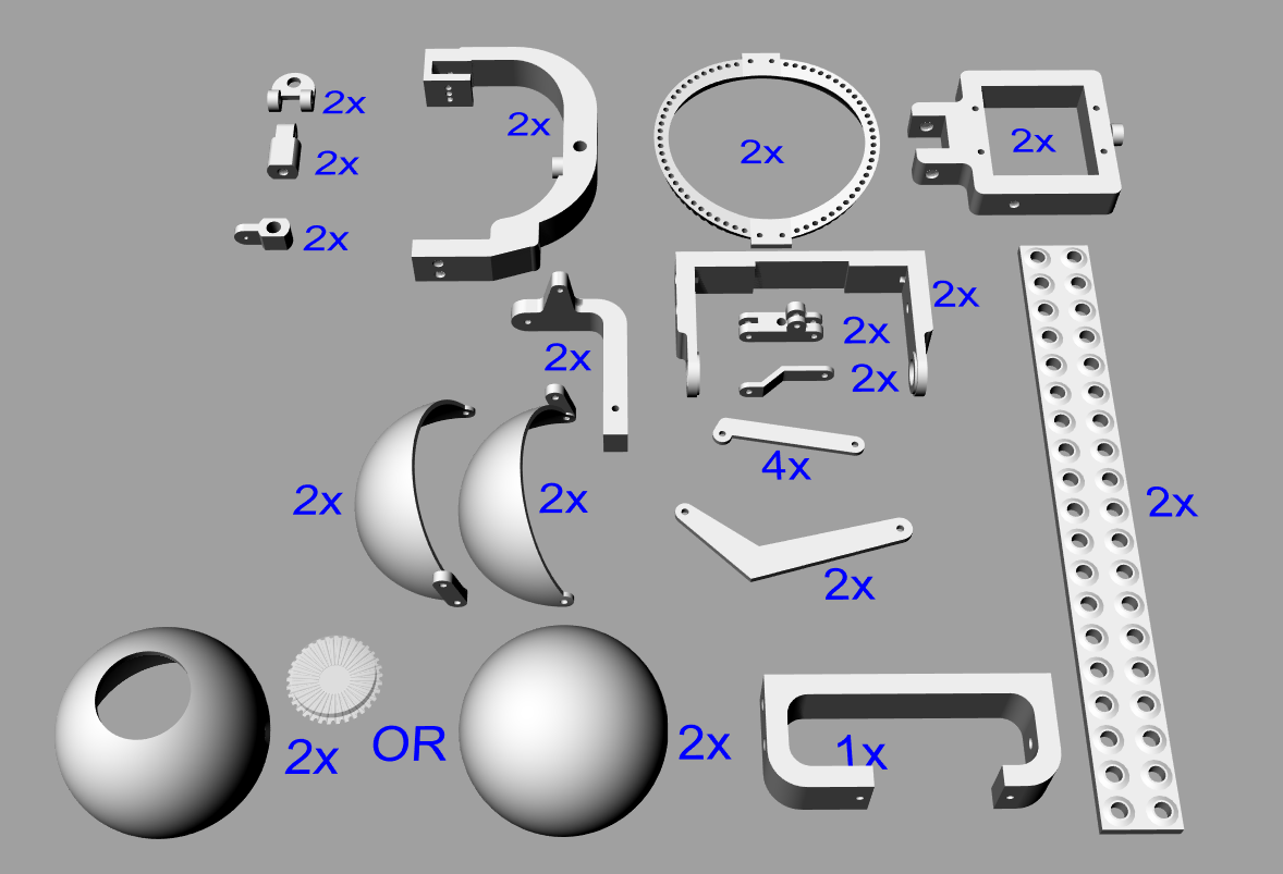
Printing:
See the following image to see how many parts you have to print from each piece I printed everything in ABS, but PLA may also work.
Post-Printing:
Tools required:
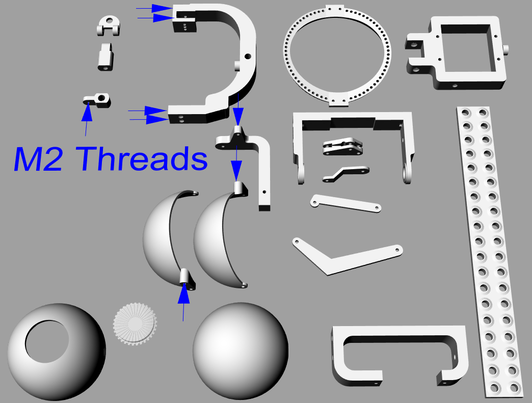
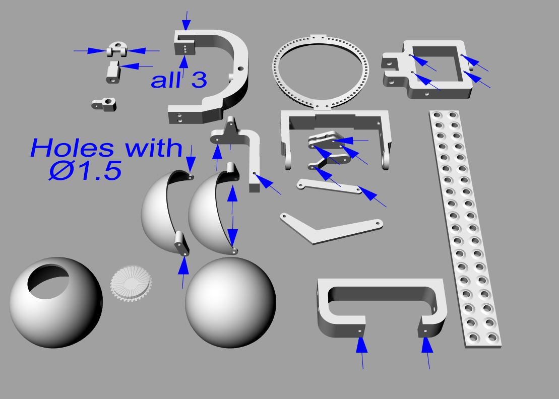
Drill 1.5 mm – to calibrate the core holes for the M2 threads and the hinge holes
Thread Tab M2
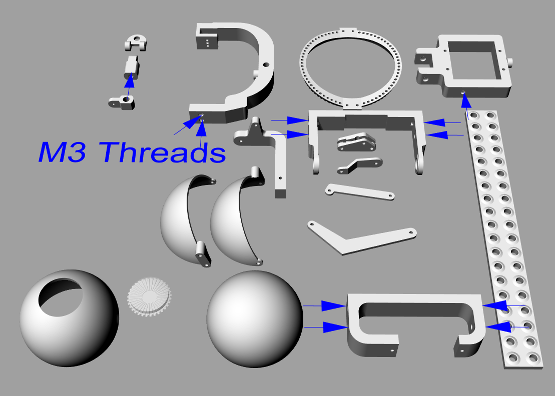
Drill 2.4 mm – to calibrate the core holes for the M3 threads
Thread Tab M3 (see the images at the end of the gallery for details)
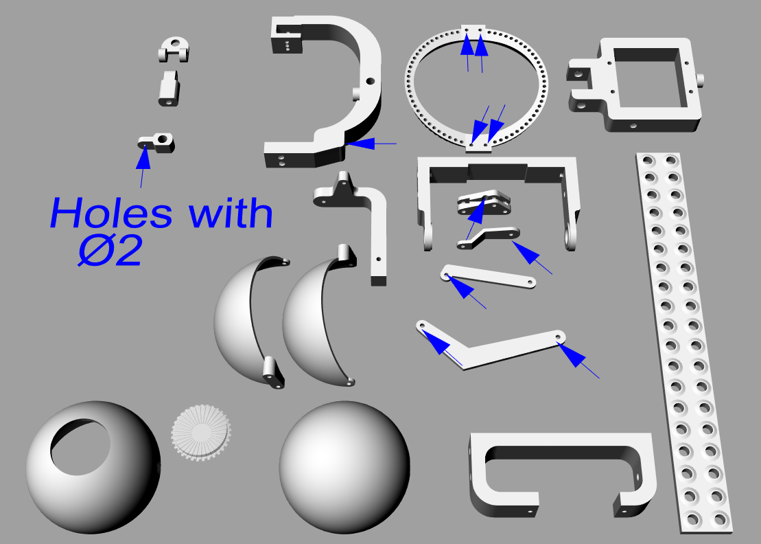
Drill 2 mm to calibrate some holes (see the images at the end of the gallery for details)
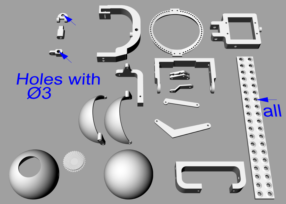
Drill 3 mm to calibrate some holes (see the images at the end of the gallery for details)
Set of small metal files.
Parts needed:
Cyan Acrylate Glue
12 Screws M2 x 4 DIN7985 (ISO7045)
14 Screws M3 x 6 DIN7985 (ISO7045)
4 Worm screws M3 x 3 DIN915 as adjustable eye lid hinges
2 Thread rods M3 (length depending on the desired eye distance – in between 20 and 50 mm)
4 M3 nuts
Piece of steel wire 1.9 mm (5 cm or actually 2 x 24mm) for the eye slider guide
Piece of copper wire 1,5mm (30 cm) for the lid axes and the slider hinge axes
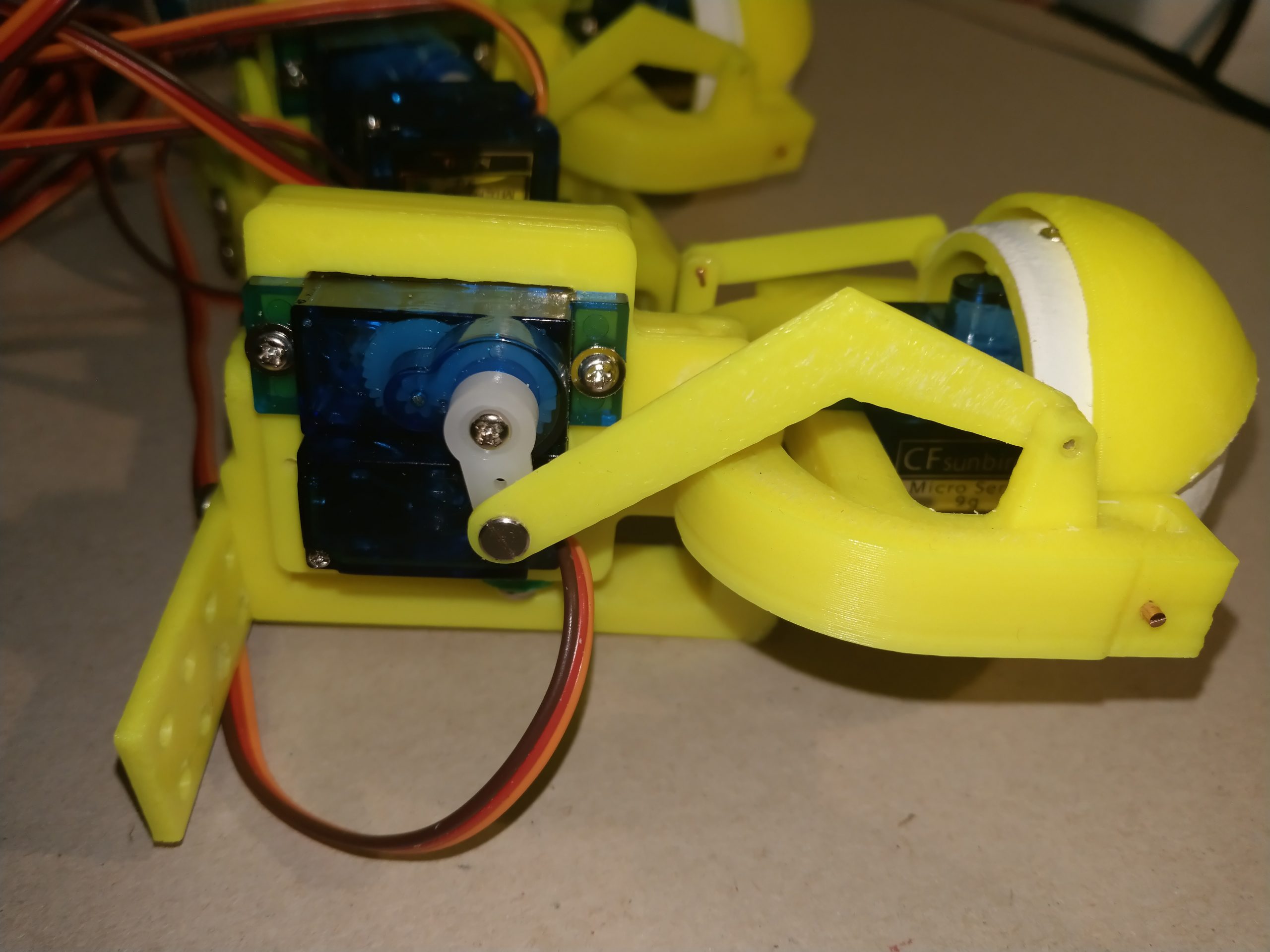
7 SG90 Servos preferrable with slanted cable outlet like from sunbird.
Preparation of the printed parts:
All holes need to be calibrated according to the images shown in the gallery.
Also parts that are intended to fit together need to be re-worked at the fitting areas with a metal file to get a close, but easy moving fit. If fittings become too lose, the mechanics will not work properly. If fittings are still going too hard, it has the same effect. In other words, precision is very important.
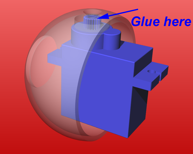
Mounting the eye balls onto the servos:
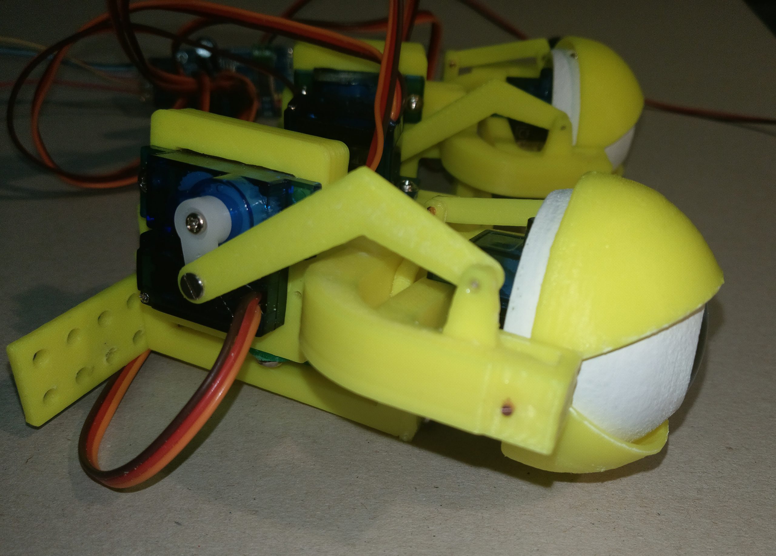
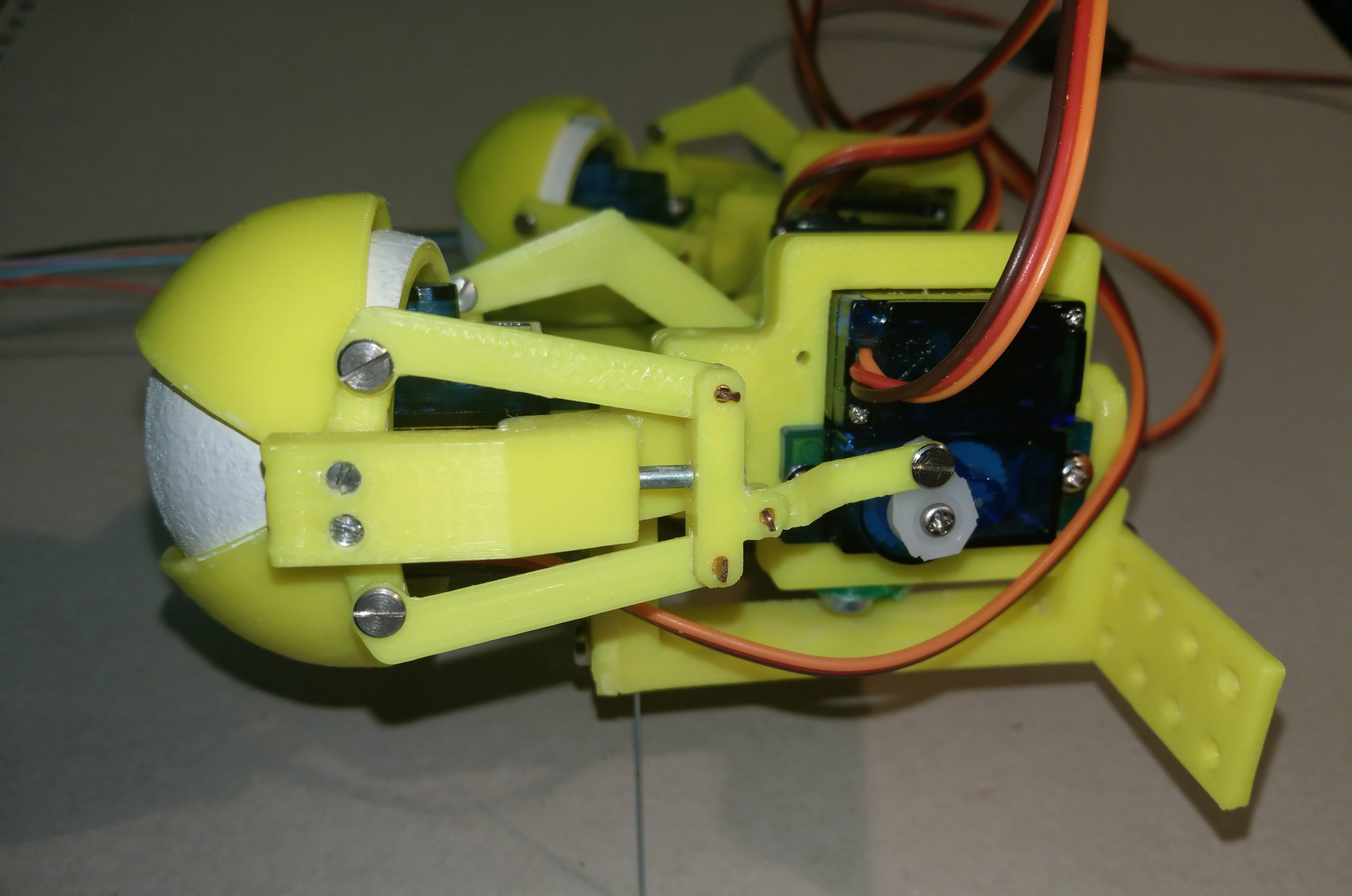
To mount the eye balls onto the SG90 servos, you need to fix the eye ball somehow onto the servo axis. Printing the star lock into the eye balls is simply too in-accurate. Therefore the diameters for the eye-ball fit is a little larger than the servo axis. But this means the eye ball will not be tight on the servo axis. As soon as the servo reaches one of the mechanical stops, it will move on the connection point, even if the screw is tightened well. So I solved this problem by putting a small droplet of cyan acrylate glue into the connection point, put the eye ball aligned onto the servo axis when the servo is exactly in the middle position, tightened with the screw and wait until the glue was cured. Because the star joint on the SG90 is out of polypropylene, the glue will not fix the Eye ball onto the Servo. THis makes it un-mountable.
Mounting the guide wire into the eye lid lever slider:
The 1.9mm steel guiding wire is used to make sure, the slider moves parallel to the eye middle axis, so the eye lid levers and the servo-slider connection lever do not wobble around. The guiding wire needs to slip inside the eye lid holding frame and needs to be fixed inside the lever slider. To achieve this I used a very small droplet of cyan acrylate glue to fix the steel wire piece (23 mm long) inside the middle hole of the slider. After curing make sure the steel wire moves easily inside the guide hole in the eye lid holding frame.
Mount the lid axes into the eye lid frame
You need two 1.5 x 2.7 mm copper wire pieces per eye as axes for the eye lids. You need to glue them into the eye lid frame frame with cyan acrylate glue.
Mount the eye ball vertical hinge angle
To mount the eye balls into the eye lid frame, you need a 1.5 mm x 10 mm long copper wire. To fix the wire it may be helpful to glue it on one side into the frame.
Installing the hinge wires to connect the lid levers and the servo lever to the lid lever slider
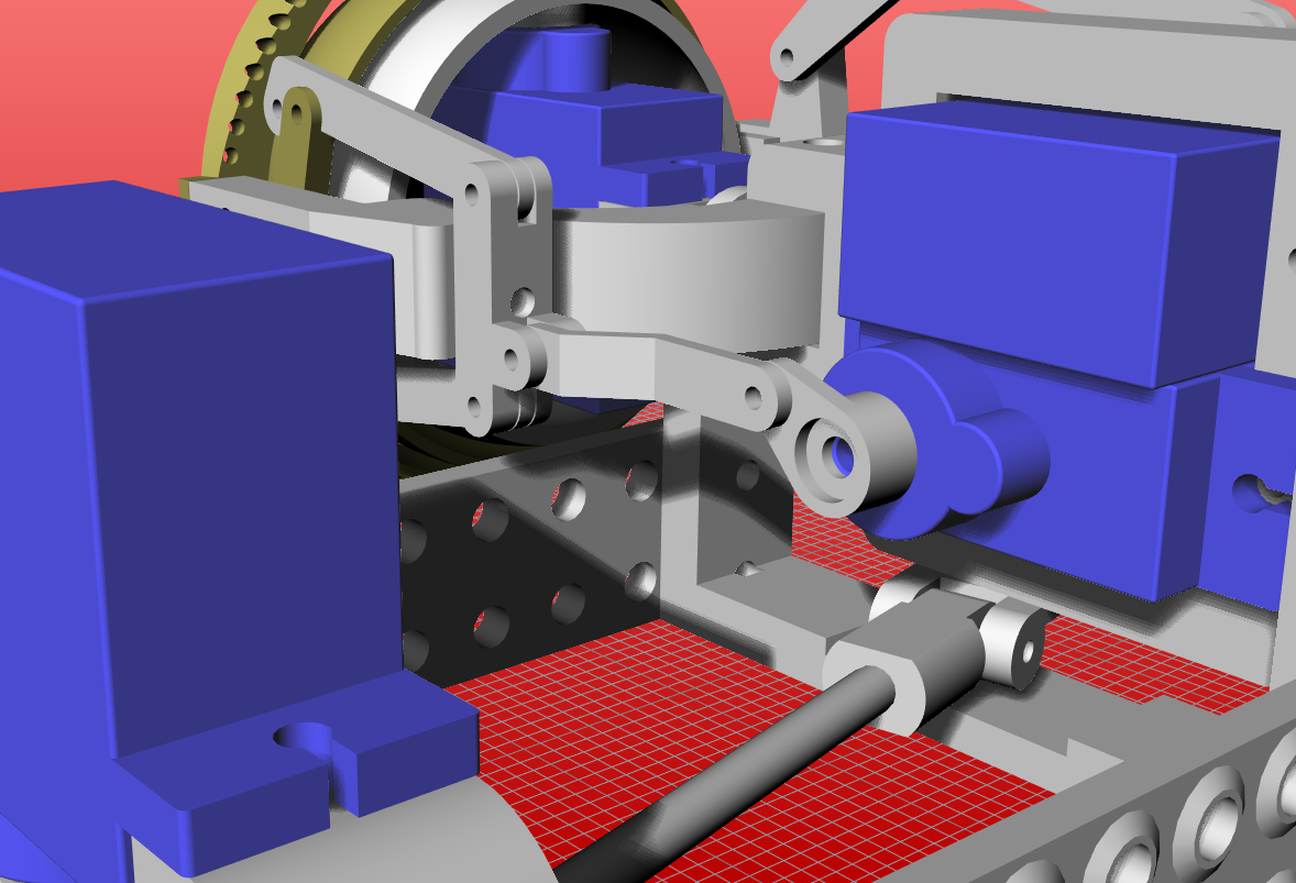
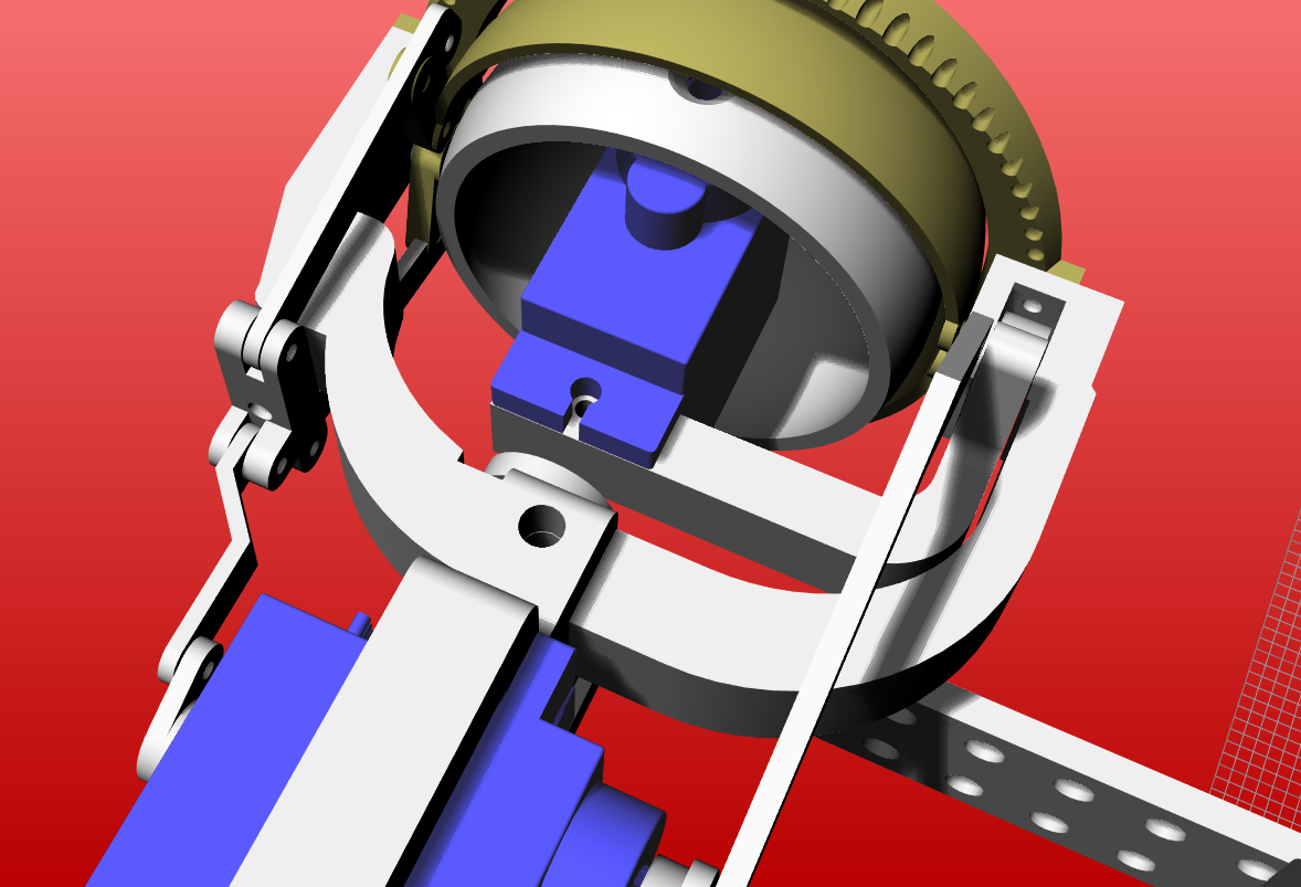
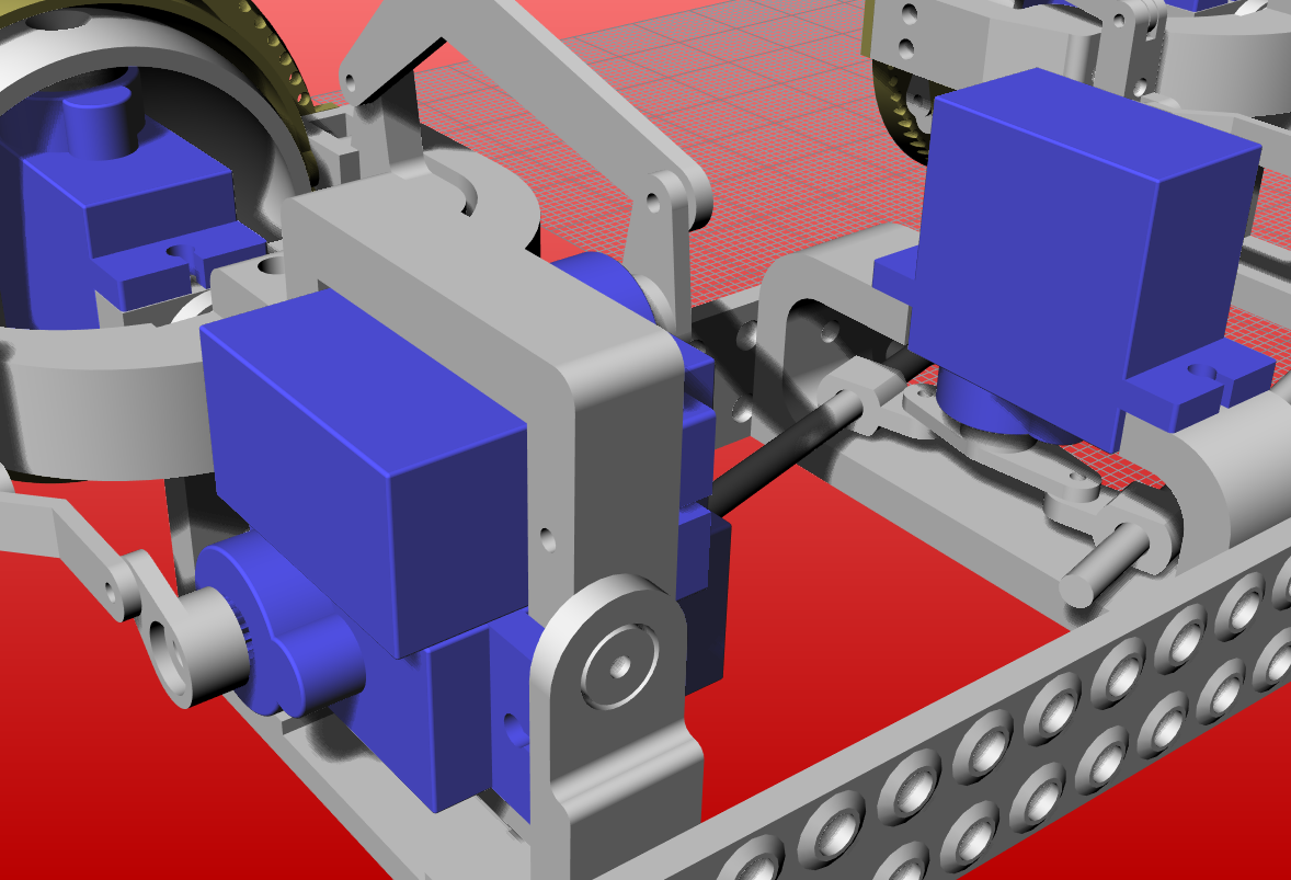
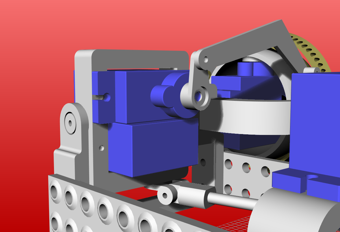
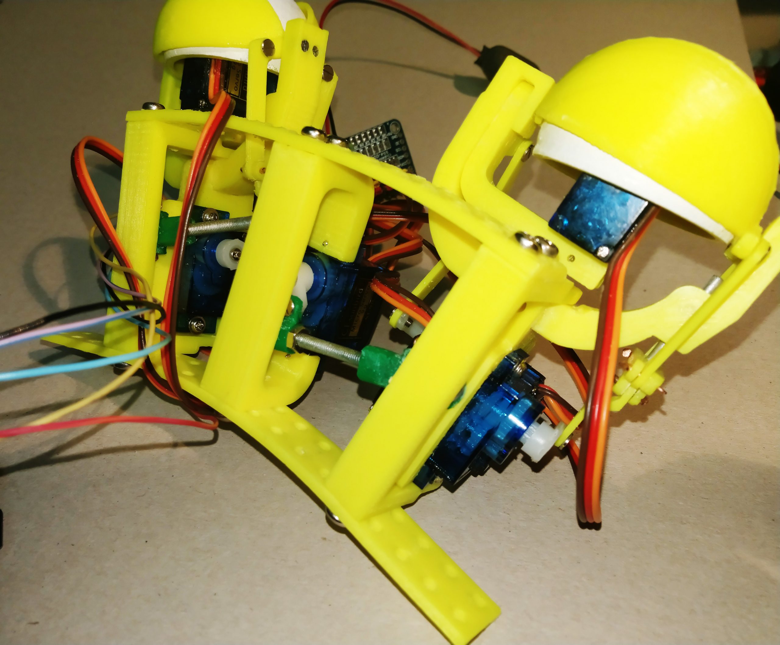
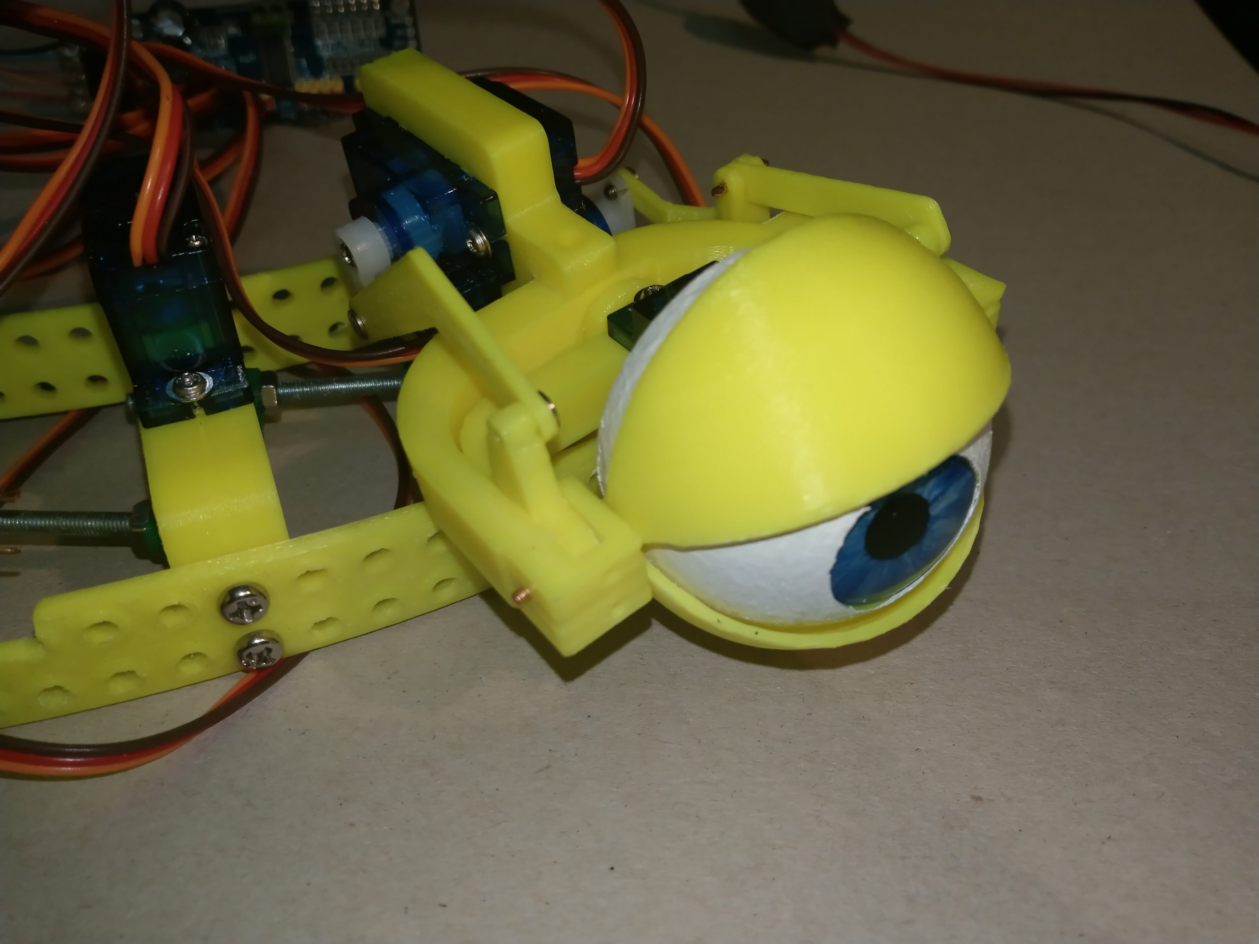
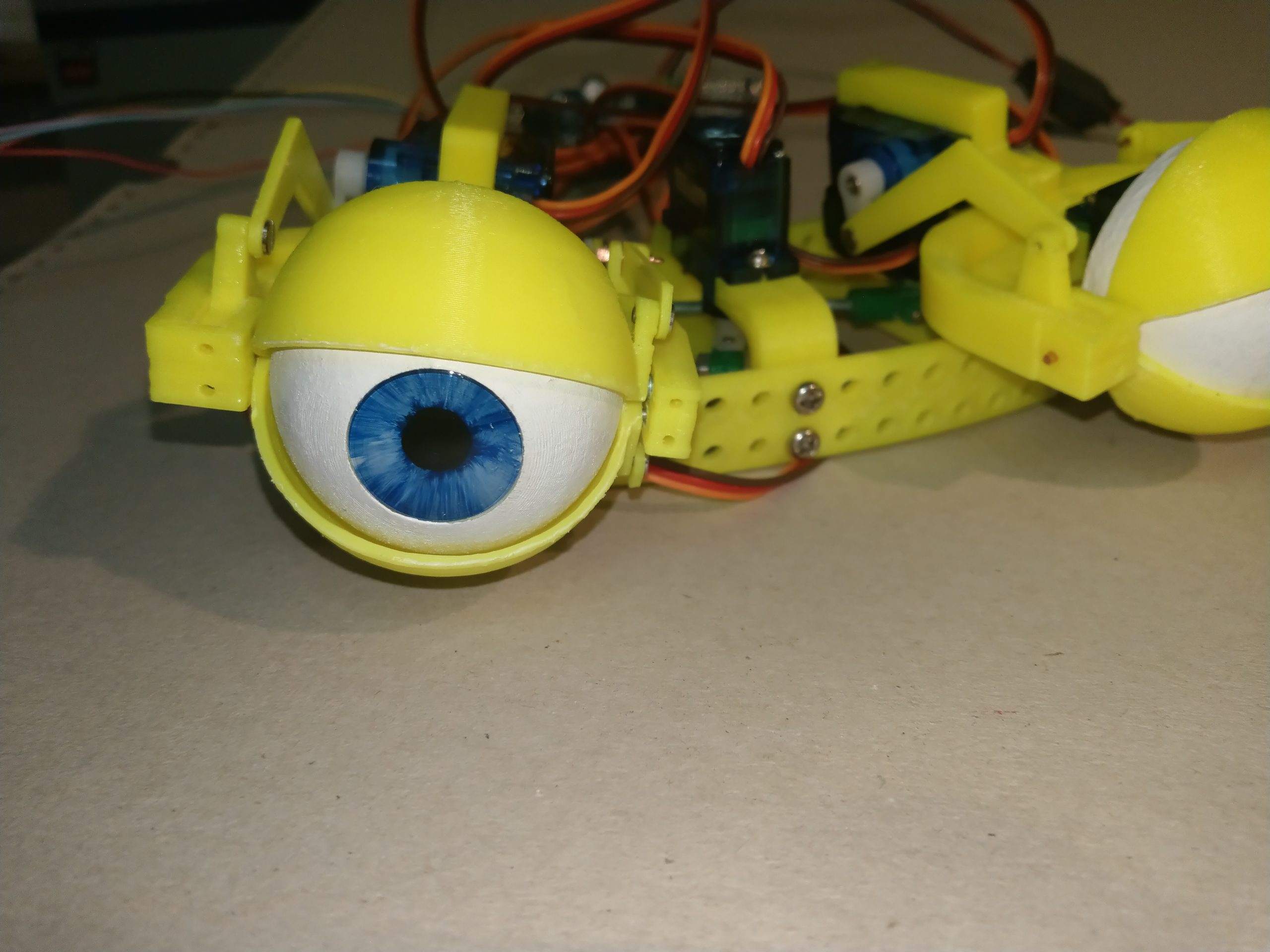
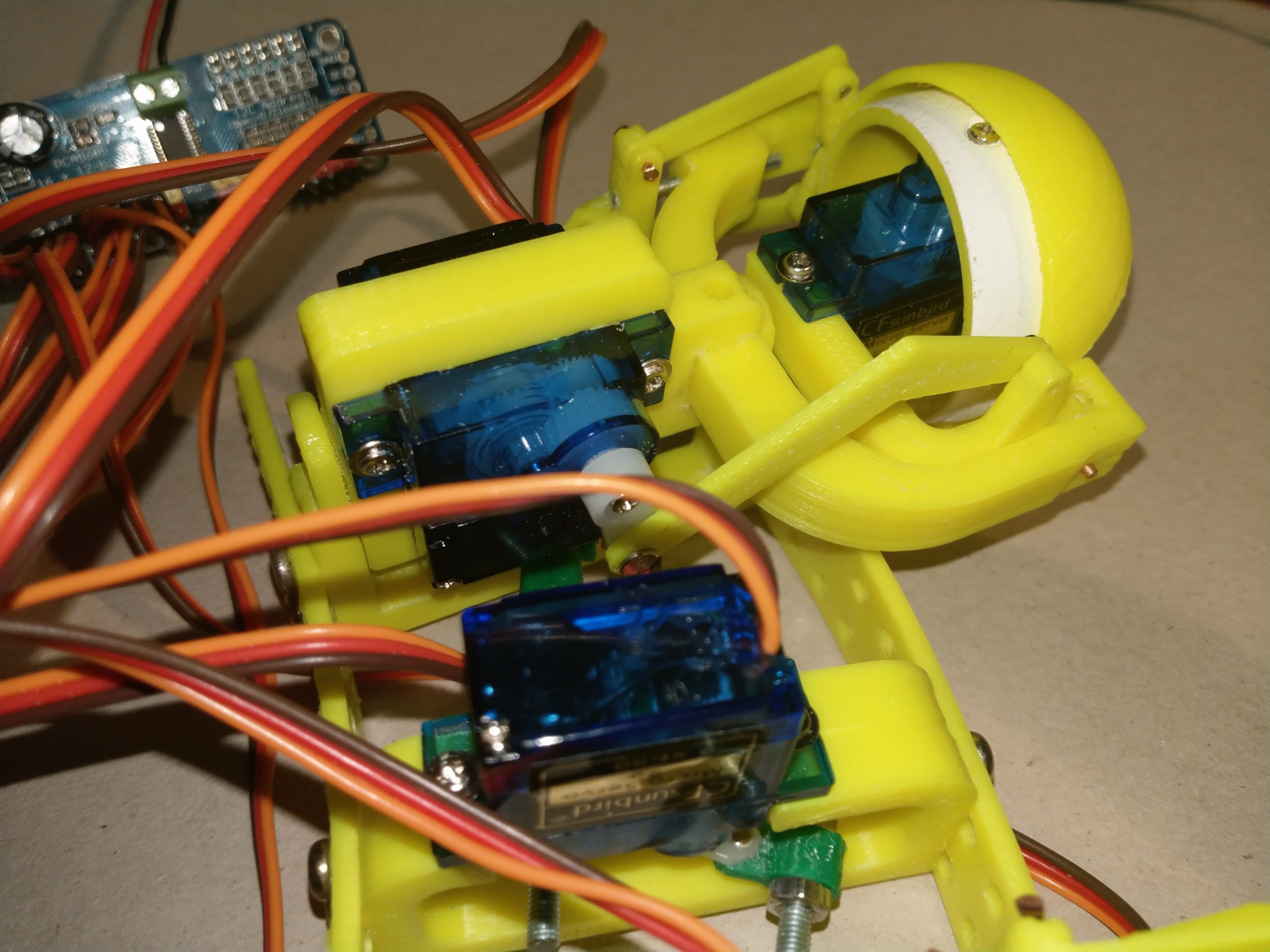
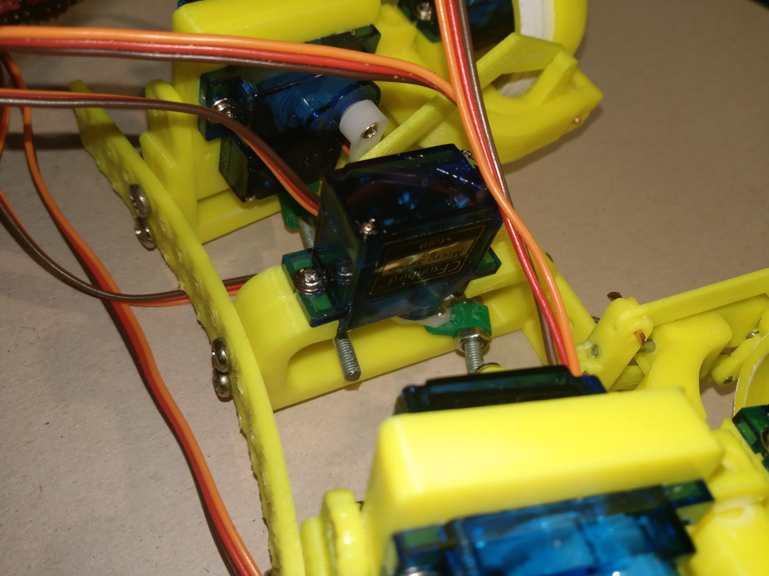
The hinge axes I realized with small pieces of 1.5 mm copper wired. To make sure the wires do not slip out of the holes, I squeezed/pinched them at th end with flat pliers. This is visible in the photos of the eye mechanics – see the gallery.
Mounting everything together
In hope the rest of the part installation is straight forward, I do not describe it in detail. If you you can’t get along with it, let me know, so I will extend the instructions.
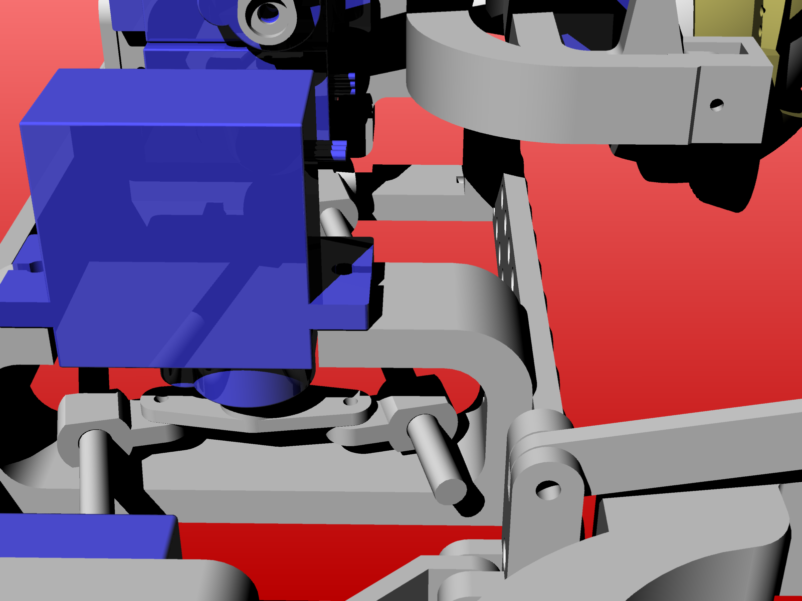
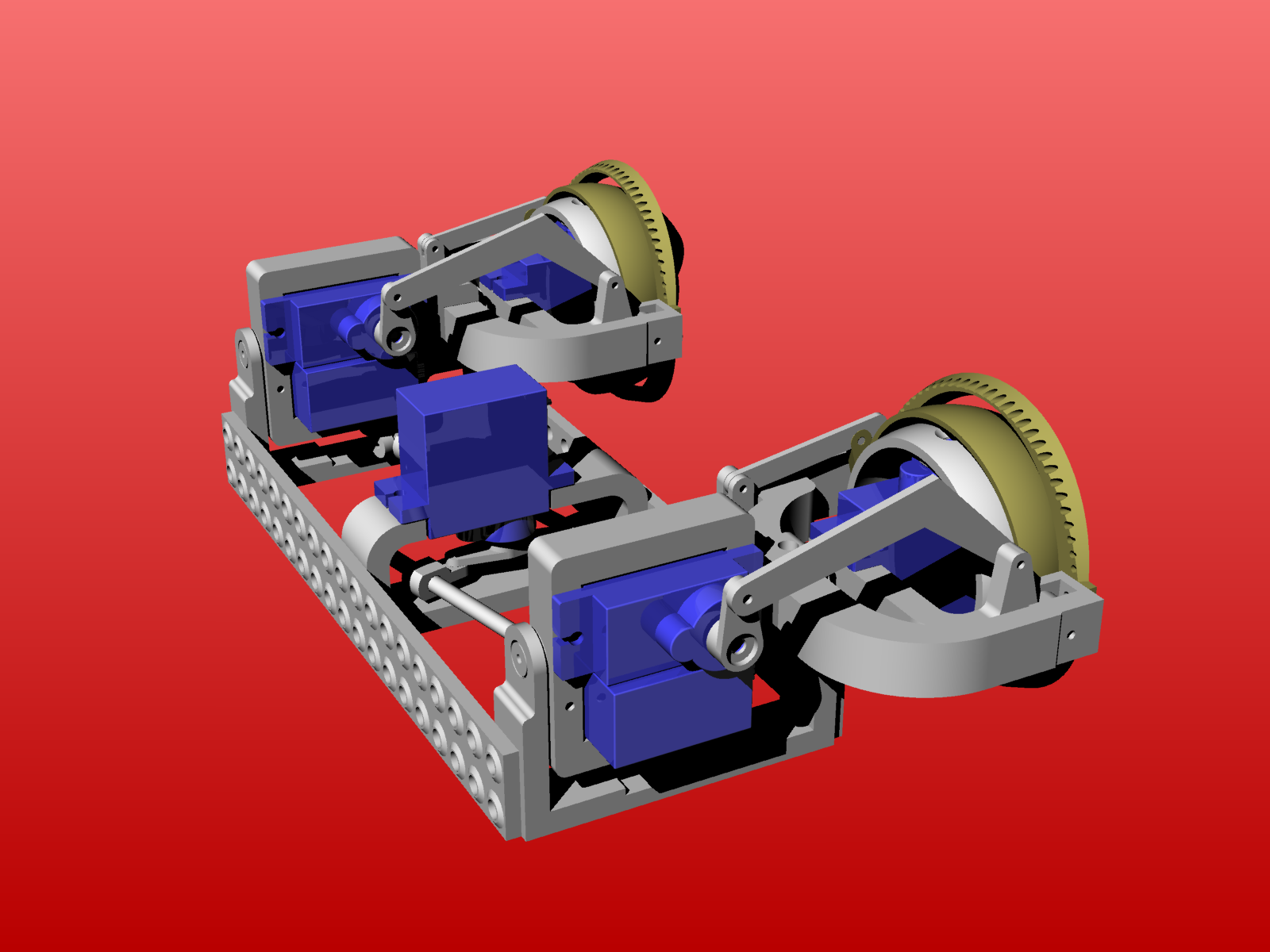
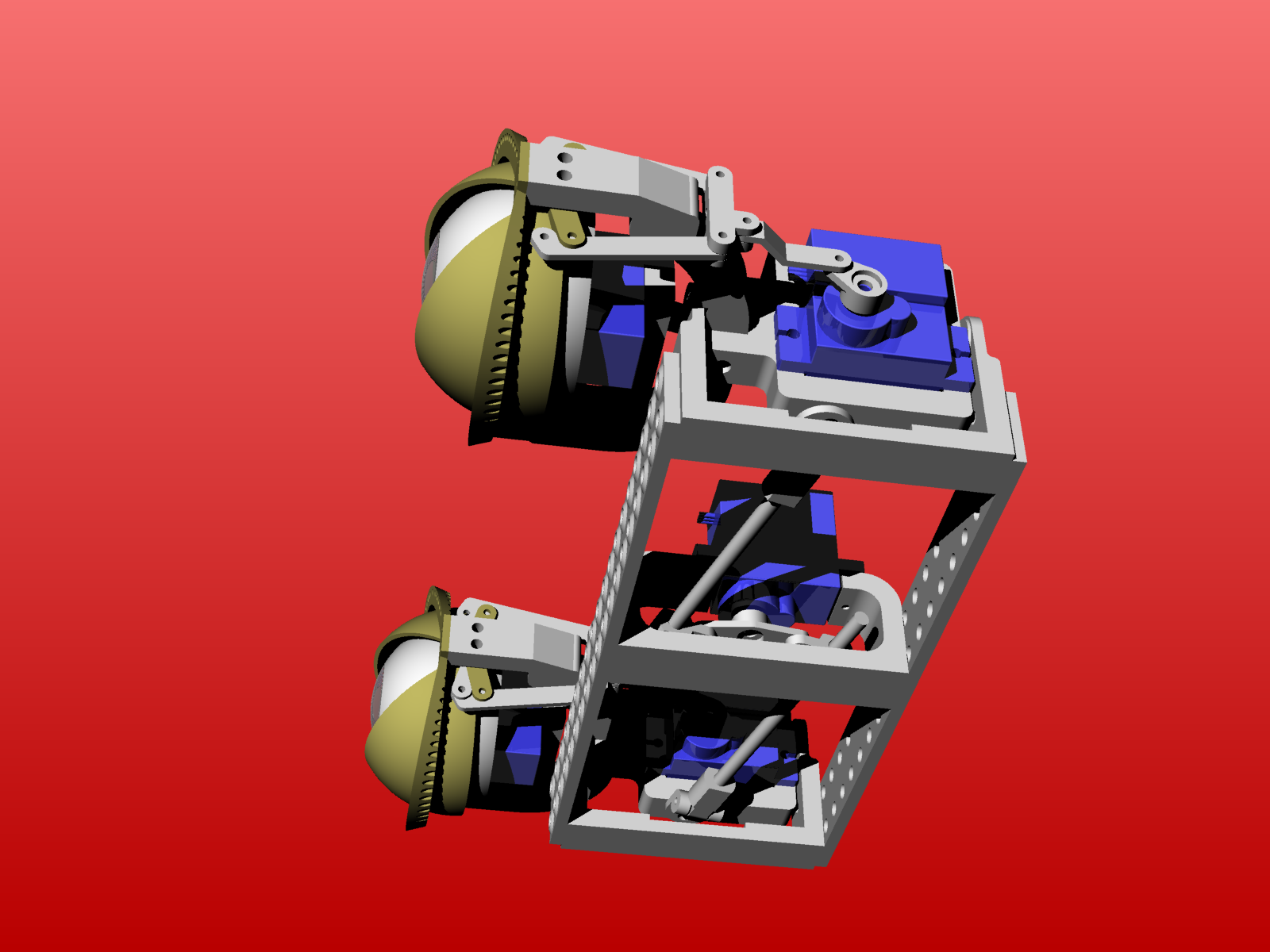
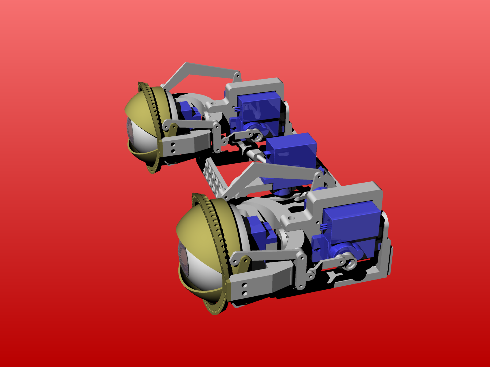
here some images from the details
Thanks you for the info!
I Have printed the part files and will begin assembly soon.
Where do I get the software? I am using Arduino.
Thanks Again
Dear Leslie,
unfortunately there is no software for Arduino. Since the project uses several devices, of which some the arduino does not have, the whole project is based on a Raspberry Pi or OrangePI under Linux. The belonging software you will find on my web site.
Hi, Thank you for your work, I have downloaded the files and I’m eager to start but there appears to be a file missing. The plate that holds the upper servos and connects to the back of the eye frame arrangement.
Dear Martyn, many thanks for the hint and sorry for the missing part. Obviously I forgot to pack one piece. Meanwhile I added the part to the downloadable zip file, so all necessary parts should be available now via: https://bechele.de/wp-content/uploads/2022/08/eye-mechanics-one-eye.zip
Greetings Rolf